2 ramp function generator, 3 operating range of the pid process controller, 2 ramp function generator 0 – Lenze 8400 TopLine User Manual
Page 1610: 3 operating range of the pid process controller 0, 19 function library
19
Function library
19.1
Function blocks
1610
Lenze · 8400 TopLine · Reference manual · DMS 6.0 EN · 06/2014 · TD05/TD14
_ _ _ _ _ _ _ _ _ _ _ _ _ _ _ _ _ _ _ _ _ _ _ _ _ _ _ _ _ _ _ _ _ _ _ _ _ _ _ _ _ _ _ _ _ _ _ _ _ _ _ _ _ _ _ _ _ _ _ _ _ _ _ _
19.1.138.2 Ramp function generator
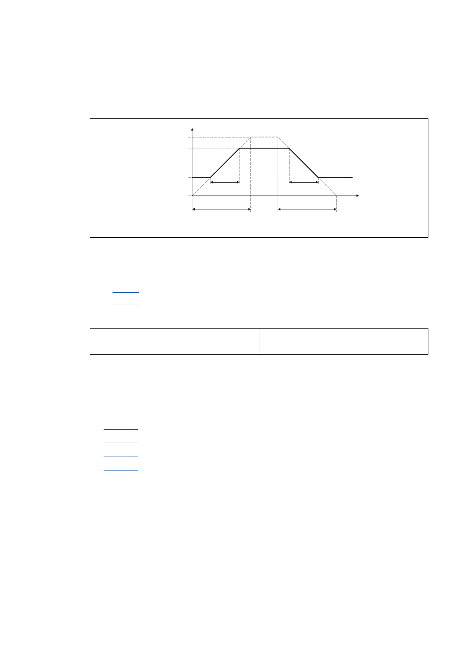
The PID output is led via a ramp function generator with linear characteristic. This serves to transfer
setpoint step-changes at the PID output into a ramp which should be as steep as possible.
[19-60] Acceleration and deceleration times
• t
ir
and t
if
are the desired times for changing between w1 and w2.
• The ramps for acceleration and deceleration can be set individually.
•
: Acceleration time t
ir
•
: Deceleration time t
if
• The t
ir
/t
if
values are converted into the required Ti times according to the following formula:
• The ramp function generator is immediately set to "0" by setting bInAct to TRUE.
19.1.138.3 Operating range of the PID process controller
The value range of the input signal nSet_a and thus the operating range of the PID process controller
can be limited with the following parameters:
•
: Pos. maximum (default setting: 199.99 %)
•
: Pos. minimum (default setting: 0.00 %)
•
: Neg. minimum (default setting: 0.00 %)
•
: Neg. maximum (default setting: 199.99 %)
w1, w2 = change of the main setpoint as a function of t
ir
and t
if
RFG-OUT = output of the ramp function generator
RFG-OUT
100 %
w2
w1
t
0 %
t
ir
T
ir
t
if
T
if
T
ir
t
ir
100 %
w2 w1
–
-----------------------
⋅
=
T
if
t
if
100 %
w2 w1
–
-----------------------
⋅
=