C01122 | sync phase position, C01123 | sync window, C01124 | sync correction width – Lenze 8400 TopLine User Manual
Page 1166: C01122, C01123, C01124, Rmining, The poin, 17 parameter reference
17
Parameter reference
17.2
Parameter list | C01122
1166
Lenze · 8400 TopLine · Reference manual · DMS 6.0 EN · 06/2014 · TD05/TD14
_ _ _ _ _ _ _ _ _ _ _ _ _ _ _ _ _ _ _ _ _ _ _ _ _ _ _ _ _ _ _ _ _ _ _ _ _ _ _ _ _ _ _ _ _ _ _ _ _ _ _ _ _ _ _ _ _ _ _ _ _ _ _ _
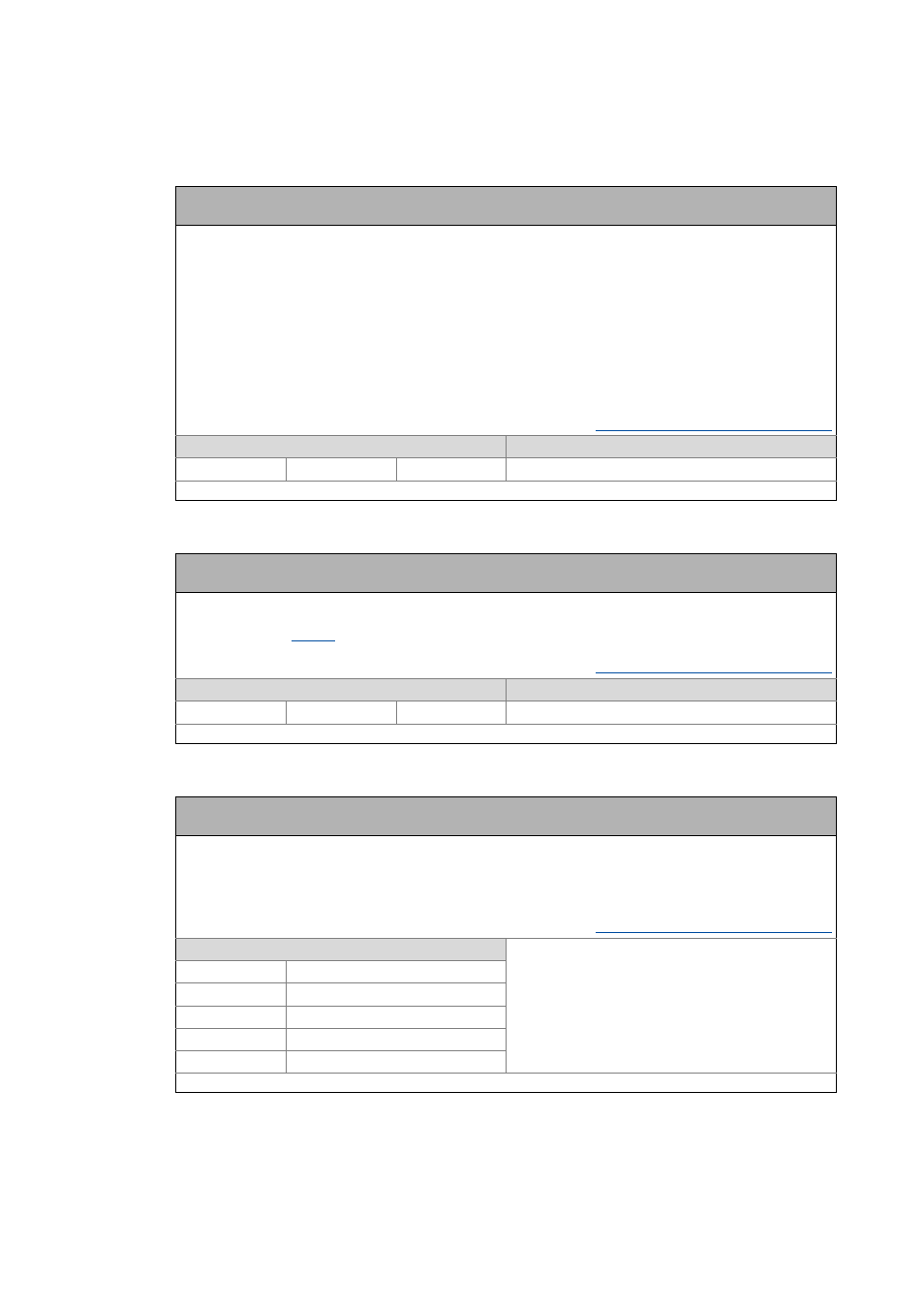
C01122
C01123
C01124
Parameter | Name:
C01122 | Sync phase position
Data type: UNSIGNED_16
Index: 23453
d
= 5B9D
h
Phase position for device synchronisation
• The phase position determines the zero-time of the internal system cycle with regard to the synchronisation
signal (bus cycle). Since PDO processing is an inherent part of the system part of the application, the instant of
acceptance of the PDOs is postponed as well by a changed phase position.
• With a setting = 0, the system cycle starts simultaneously with the synchronisation signal.
• With a setting > 0, the internal system cycle starts earlier by the set time with regard to the synchronisation
signal (the phase position acts negatively).
• Intelligent communication modules define the optimal time with activated synchronisation by themselves. In
this case, a manual change is not possible.
• The decisive factor for defining C01122 is the time where all nodes are provided with valid PDOs.
Example: If the phase position is set to 550 μs, the system part of the application starts 550 μs before the arrival of
the synchronisation signal.
Synchronisation of the internal time base
Setting range
(min. value | unit | max. value)
Lenze setting
0
μs
1000 0 μs
Read access Write access CINH PLC STOP No transfer COM MOT
Scaling factor: 1
Parameter | Name:
C01123 | Sync window
Data type: UNSIGNED_16
Index: 23452
d
= 5B9C
h
Time slot for monitoring the synchronisation signal or the phase position
• The synchronisation signal or the current phase position must be within this time slot around the corresponding
expected value (
).
• With the setting "1000 μs" there will be no monitoring.
Synchronisation of the internal time base
Setting range
(min. value | unit | max. value)
Lenze setting
0
μs
10000 100 μs
Read access Write access CINH PLC STOP No transfer COM MOT
Scaling factor: 1
Parameter | Name:
C01124 | Sync correction width
Data type: UNSIGNED_8
Index: 23451
d
= 5B9B
h
Correction increment for device synchronisation
• If the cycle times of the synchronisation signal differs and phase-locken loop (PLL) differ from each other, this
setting defines the measure the phase-locking loop is reset with.
• If synchronisation is not reached, select a higher correction constant.
• The optimum setting depends on quartz precision and must be determined empirically if required.
Synchronisation of the internal time base
Selection list
(Lenze setting printed in bold)
1 80ns
2 160ns
3 240ns
4 320ns
5 400ns
Read access Write access CINH PLC STOP No transfer COM MOT
Scaling factor: 1