2 possible settings via dip switch, 1 activating the bus terminating resistor, Activating the bus terminating resistor – Lenze 8400 TopLine User Manual
Page 753: 12 system bus "can on board
Lenze · 8400 TopLine · Reference manual · DMS 6.0 EN · 06/2014 · TD05/TD14
753
12
System bus "CAN on board"
12.2
Possible settings via DIP switch
_ _ _ _ _ _ _ _ _ _ _ _ _ _ _ _ _ _ _ _ _ _ _ _ _ _ _ _ _ _ _ _ _ _ _ _ _ _ _ _ _ _ _ _ _ _ _ _ _ _ _ _ _ _ _ _ _ _ _ _ _ _ _ _
12.2
Possible settings via DIP switch
The following settings for the "CAN on board" system bus can be made via the front panel DIP
switches:
Lenze setting: All DIP switches are in the "OFF" position
Tip!
The current DIP switch settings are displayed in code
Bit 15 indicates that the setting of the DIP switches has been accepted when the device or
the 24V supply has been switched on.
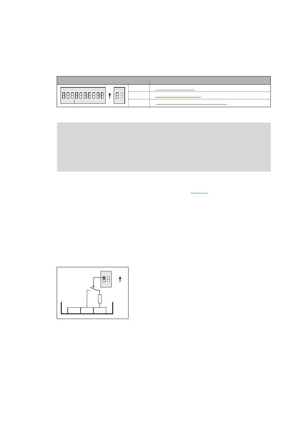
12.2.1
Activating the bus terminating resistor
The system bus must be terminated between CAN low and CAN high at the first and last physical
node each by a resistor (120 Ω).
The 8400 controller is provided with an integrated bus terminating resistor, which can be activated
via the DIP switch labelled with "CA":
[12-1] Activation of the integrated bus terminating resistor
DIP switch
Possible settings/detailed information
a ... c
1 ... 64
CA
Activating the bus terminating resistor
Note!
• The DIP switch settings are accepted if a node address is unequal zero when the device
or the 24-V supply is switched on by the DIP address.
• If all DIP switches are OFF when the device or the 24 V supply is switched on, the
setting of the baud rate and node address are read out of the parameter
set/parameter.
R
R
CA
AB
c b a 64 32 16 8 4 2 1
Baud
CAN Address
OFF
ON
• OFF = bus terminating resistor is inactive
• ON = bus terminating resistor is active
R
R
CA
AB
OFF
ON
120
Ù
CG
CL
CH
X1