6 following error monitoring system, Following error monitoring system, 9basic drive functions (mck) – Lenze 8400 TopLine User Manual
Page 597
Lenze · 8400 TopLine · Reference manual · DMS 6.0 EN · 06/2014 · TD05/TD14
597
9
Basic drive functions (MCK)
9.4
Basic settings
_ _ _ _ _ _ _ _ _ _ _ _ _ _ _ _ _ _ _ _ _ _ _ _ _ _ _ _ _ _ _ _ _ _ _ _ _ _ _ _ _ _ _ _ _ _ _ _ _ _ _ _ _ _ _ _ _ _ _ _ _ _ _ _
9.4.6
Following error monitoring system
The difference between set position and actual position is called the following error. Ideally, the
following error should be "0". The set position is created by the internal definition of the traversing
profiles of the Motion Control Kernel. The actual position is created by the integration of the speed
supplied by the position encoder. If the position control is adjusted optimally, only a minimum
following error arises which is always compensated dynamically and not increases continuously.
Certain processes, however, require that a defined limit as a difference between set position and
actual position is not exceeded. If it is exceeded, it may have been caused by a mechanical blocking
in the machine and the system part is not situated at the position defined at that time. In such a
case, it makes sense to activate the "Fault" error response to make the motor torqueless.
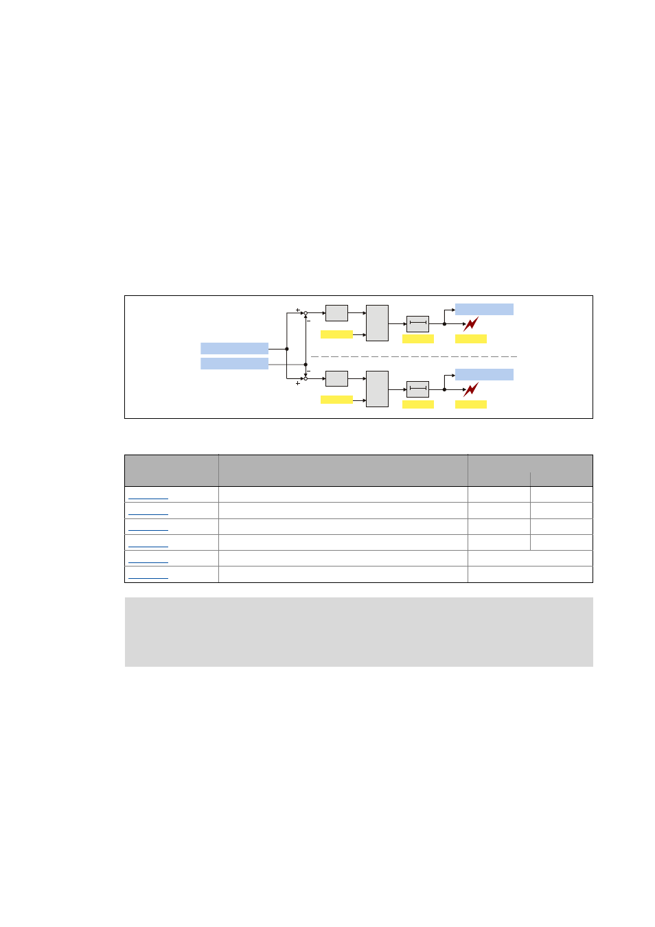
In the 8400 TopLine controller, two independent following error monitoring systems can be
parameterised:
[9-19] Two-channel following error monitoring system
Tip!
In certain situations (e.g. dynamic acceleration of the load), higher system-dependent
following errors occur than while approaching the target position.
In order that no error is triggered during acceleration and a close tolerance limit can be
monitored all the same at standstill in the target, the addressing of the following error
monitoring system can be decelerated. Thus, dynamic processes or torque impulses
occurring for short periods can be "masked out".
&
GQ3RV6HW9DOXHBS
GQ0RWRU3RV$FWBS
DEV
$!%
$
%
W
&
&
&
DEV
$!%
$
%
W
&
&
E)ROORZ(UU/LP
E)ROORZ(UU/LP
Parameter
Info
Lenze setting
Value Unit
MCK: Following error limit 1
0.0000 units
MCK: Following error limit 2
0.0000 units
MCK: Following error deceleration 1
0.000 s
MCK: Following error deceleration 2
0.000 s
MCK: Resp. to following error 1
Warning
MCK: Resp. to following error 2
Warning
Note!
If the limit for the following error is set to "0.0000 units" (Lenze setting, the following
error monitoring system is not active.