8 analog signal monitor, 9 d-flipflop, Analog signal monitor – Lenze 8400 TopLine User Manual
Page 550: D-flipflop, 8technology applications
8
Technology applications
8.6
"GeneralPurpose" functions
550
Lenze · 8400 TopLine · Reference manual · DMS 6.0 EN · 06/2014 · TD05/TD14
_ _ _ _ _ _ _ _ _ _ _ _ _ _ _ _ _ _ _ _ _ _ _ _ _ _ _ _ _ _ _ _ _ _ _ _ _ _ _ _ _ _ _ _ _ _ _ _ _ _ _ _ _ _ _ _ _ _ _ _ _ _ _ _
8.6.8
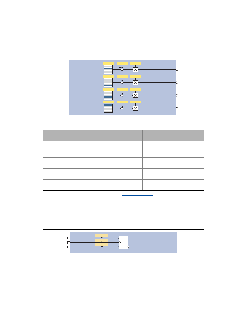
Analog signal monitor
This function serves to output four analog signals selected from a list of all analog output signals
available in the drive controller. Offset and gain of the source signals can be adjusted.
[8-30] GeneralPurpose function "Analog signal monitor"
• For a detailed functional description see the
FB.
8.6.9
D-FlipFlop
This function saves the logic status of the data input (1D) in case of an active clock edge at the clock
input (C1) and puts out its value in sequence at the output Q. If there is no active clock edge, the
input value is not accepted.
[8-31] GeneralPurpose function "D-FlipFlop" (clock-edge controlled)
• For a detailed functional description see FB
.
nGPSignalOut1_a
C00410/1
C00413/2
C00413/1
nGPSignalOut2_a
C00410/2
C00413/4
C00413/3
nGPSignalOut3_a
C00410/3
C00413/6
C00413/5
nGPSignalOut4_a
C00410/4
C00413/8
C00413/7
Parameter
Info
Lenze setting
Value Unit
L_SignalMonitor_a: Signal 1 ... 4
0: Not connected
L_SignalMonitor_a: Signal 1 offset
0.00 %
L_SignalMonitor_a: Signal 1 gain
100.00 %
L_SignalMonitor_a: Signal 2 offset
0.00 %
L_SignalMonitor_a: Signal 2 gain
100.00 %
L_SignalMonitor_a: Signal 3 offset
0.00 %
L_SignalMonitor_a: Signal 3 gain
100.00 %
L_SignalMonitor_a: Signal 4 offset
0.00 %
L_SignalMonitor_a: Signal 4 gain
100.00 %
bGPDFlipFlop_NegOut
bGPDFlipFlopOut
bGPDFlipFlop_InD
bGPDFlipFlop_InClk
bGPDFlipFlop_InClr
C1
Q
Q
1D
R
C00833/4
C00833/5
C00833/6