1 signal adaptation by means of characteristic, Signal adaptation by means of characteristic, 7i/o terminals – Lenze 8400 TopLine User Manual
Page 406
7
I/O terminals
7.3
Analog terminals
406
Lenze · 8400 TopLine · Reference manual · DMS 6.0 EN · 06/2014 · TD05/TD14
_ _ _ _ _ _ _ _ _ _ _ _ _ _ _ _ _ _ _ _ _ _ _ _ _ _ _ _ _ _ _ _ _ _ _ _ _ _ _ _ _ _ _ _ _ _ _ _ _ _ _ _ _ _ _ _ _ _ _ _ _ _ _ _
7.3.1.1
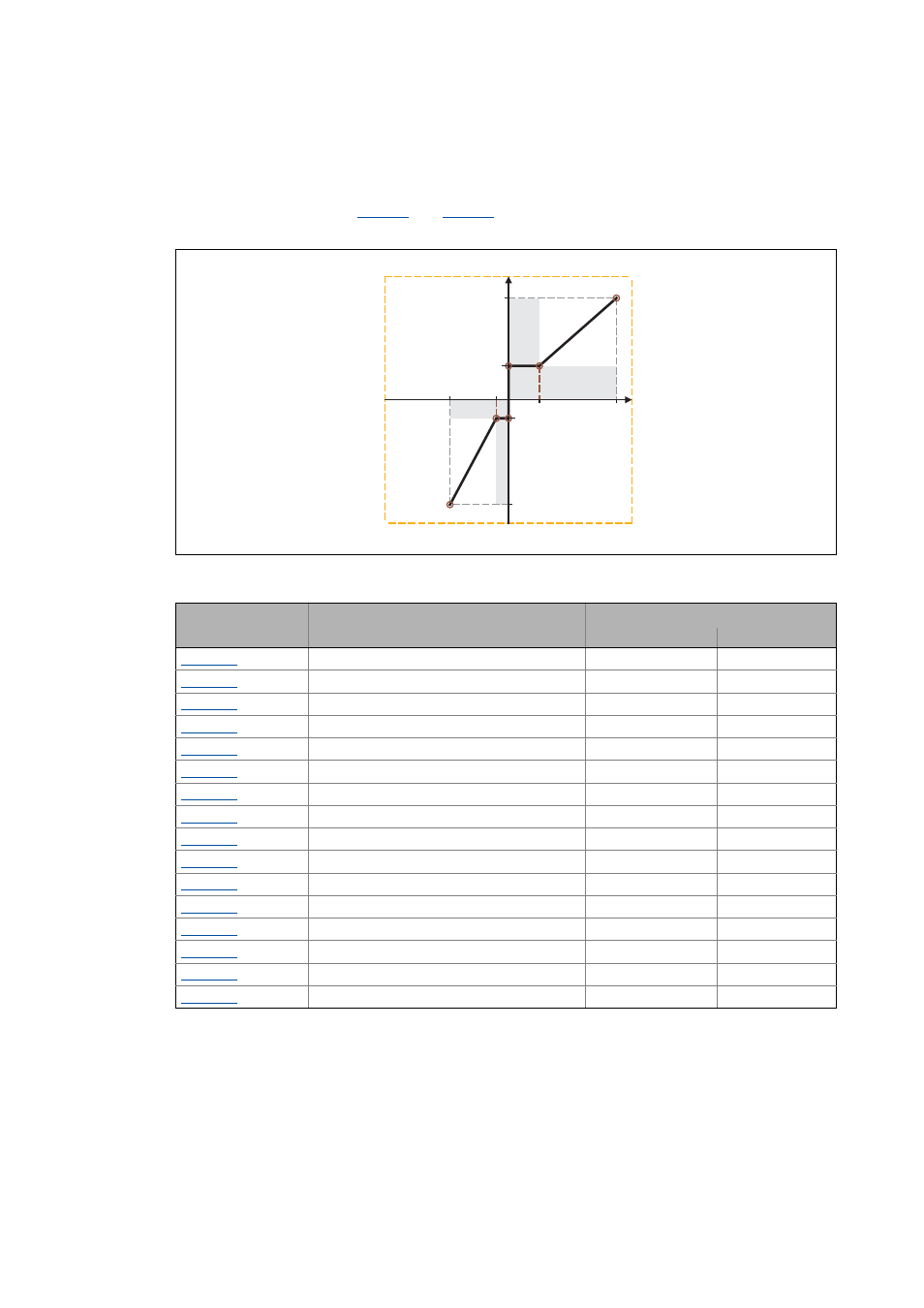
Signal adaptation by means of characteristic
According to the illustration below, an individual characteristic can be parameterised for the analog
inputs via the subcodes of
and
to provide different slopes and a dead band. Here,
the input signal corresponds to the X axis and the output signal corresponds to the Y axis:
[7-5]
Characteristic for analog inputs
In the »Engineer«, there is a parameterising dialog for entering the characteristic. This dialog also
displays the set characteristic graphically.
199.99 %
y
max
-y
max
-x
max
x
max
y
min
-y
min
199.99 %
-199.99 %
-199.99 %
Parameter
Info
Lenze setting
Value Unit
AIN1: (+y0) = min
0.00 %
AIN1: (+x0) = Dead band
1.00 %
AIN1: (-y0) = (-min)
0.00 %
AIN1: (-x0) = (-Dead band)
1.00 %
AIN1: (+ymax)
199.99 %
AIN1: (+xmax)
199.99 %
AIN1: (-ymax)
199.99 %
AIN1: (-xmax)
199.99 %
AIN2: (+y0) = min
0.00 %
AIN2: (+x0) = Dead band
1.00 %
AIN2: (-y0) = (-min)
0.00 %
AIN2: (-x0) = (-Dead band)
1.00 %
AIN2: (+ymax)
199.99 %
AIN2: (+xmax)
199.99 %
AIN2: (-ymax)
199.99 %
AIN2: (-xmax)
199.99 %