1 parameterising digital inputs as encoder inputs, Parameterising digital inputs as encoder inputs, 6encoder/feedback system – Lenze 8400 TopLine User Manual
Page 353
Lenze · 8400 TopLine · Reference manual · DMS 6.0 EN · 06/2014 · TD05/TD14
353
6
Encoder/feedback system
6.4
Frequency HTL encoder (DI1/DI2, DI6/DI7)
_ _ _ _ _ _ _ _ _ _ _ _ _ _ _ _ _ _ _ _ _ _ _ _ _ _ _ _ _ _ _ _ _ _ _ _ _ _ _ _ _ _ _ _ _ _ _ _ _ _ _ _ _ _ _ _ _ _ _ _ _ _ _ _
6.4.1
Parameterising digital inputs as encoder inputs
The function of the digital inputs DI1/DI2 and DI6/DI7 is defined via
.
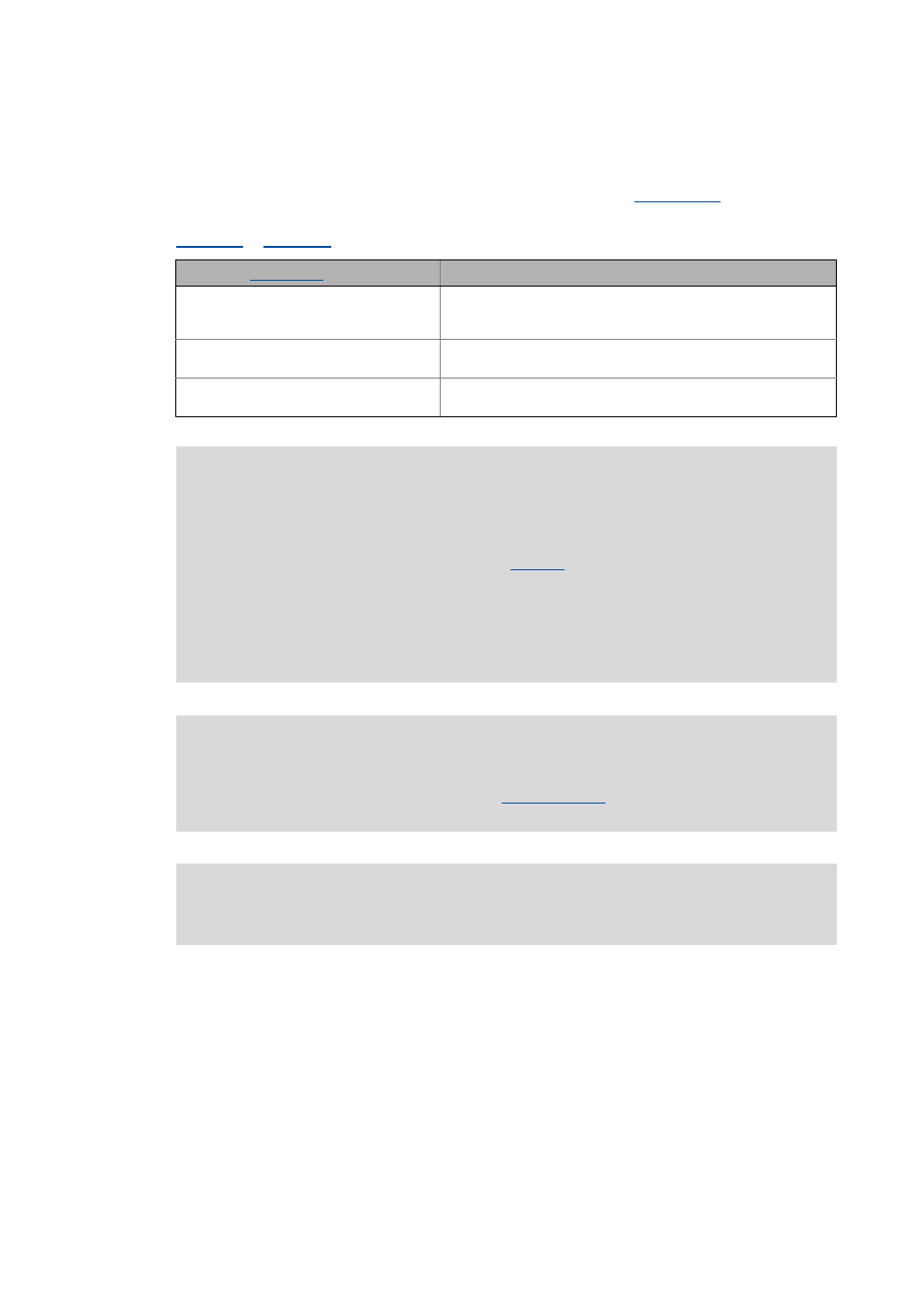
To be able to use the digital inputs as encoder inputs, select 2, 3, or 4 (Lenze recommendation: 2) in
, depending on the input terminals used.
Selection in
Function
2: DI1(6)&DI2(7)=FreqIn (2-track)
DI1/6 and DI2/7 = 2-track frequency input
• Permits a two-track evaluation of the encoder including correct
detection of the direction of rotation.
3: DI1(6)=FreqIn / DI2(7)=Direction
DI1/6 = 1-track frequency input
DI2/7 = specification of direction
4: DI1(6)=CountIn / DI2(7)=In
DI1/6 = counter input
DI2/7 = digital input
Danger!
• For single-track evaluation, make sure that the sign is correctly specified. Otherwise,
the motor may overspeed.
• If servo control (SC) or V/f control (VFCplus + encoder) are used: For safety reasons,
always select "Fault" (Lenze setting) in
as a response for the (open-circuit)
monitoring of the encoder!
• If an HTL encoder is used at the digital input terminals:
Observe the maximum input frequencies of the digital inputs!
• DI1/DI2: max. 200 kHz
• DI6/DI7: max. 10 kHz
Note!
If the digital inputs are parameterised as encoder inputs, the corresponding output
signals (bIn1/bIn2 and bIn6/bIn7) at the
system block are automatically
set to FALSE.
Wiring diagram, assignment and electrical data of the digital input terminals can be
found in the hardware manual 8400 in the chapter "technical data". The hardware
manual is stored in electronic form on the data carrier supplied with the 8400 controller.