5 masking out touch probe signals, 6 process monitoring functions, Masking out touch probe signals 9 – Lenze 8400 TopLine User Manual
Page 1509: Process monitoring functions 9, 19 function library
Lenze · 8400 TopLine · Reference manual · DMS 6.0 EN · 06/2014 · TD05/TD14
1509
19
Function library
19.1
Function blocks
_ _ _ _ _ _ _ _ _ _ _ _ _ _ _ _ _ _ _ _ _ _ _ _ _ _ _ _ _ _ _ _ _ _ _ _ _ _ _ _ _ _ _ _ _ _ _ _ _ _ _ _ _ _ _ _ _ _ _ _ _ _ _ _
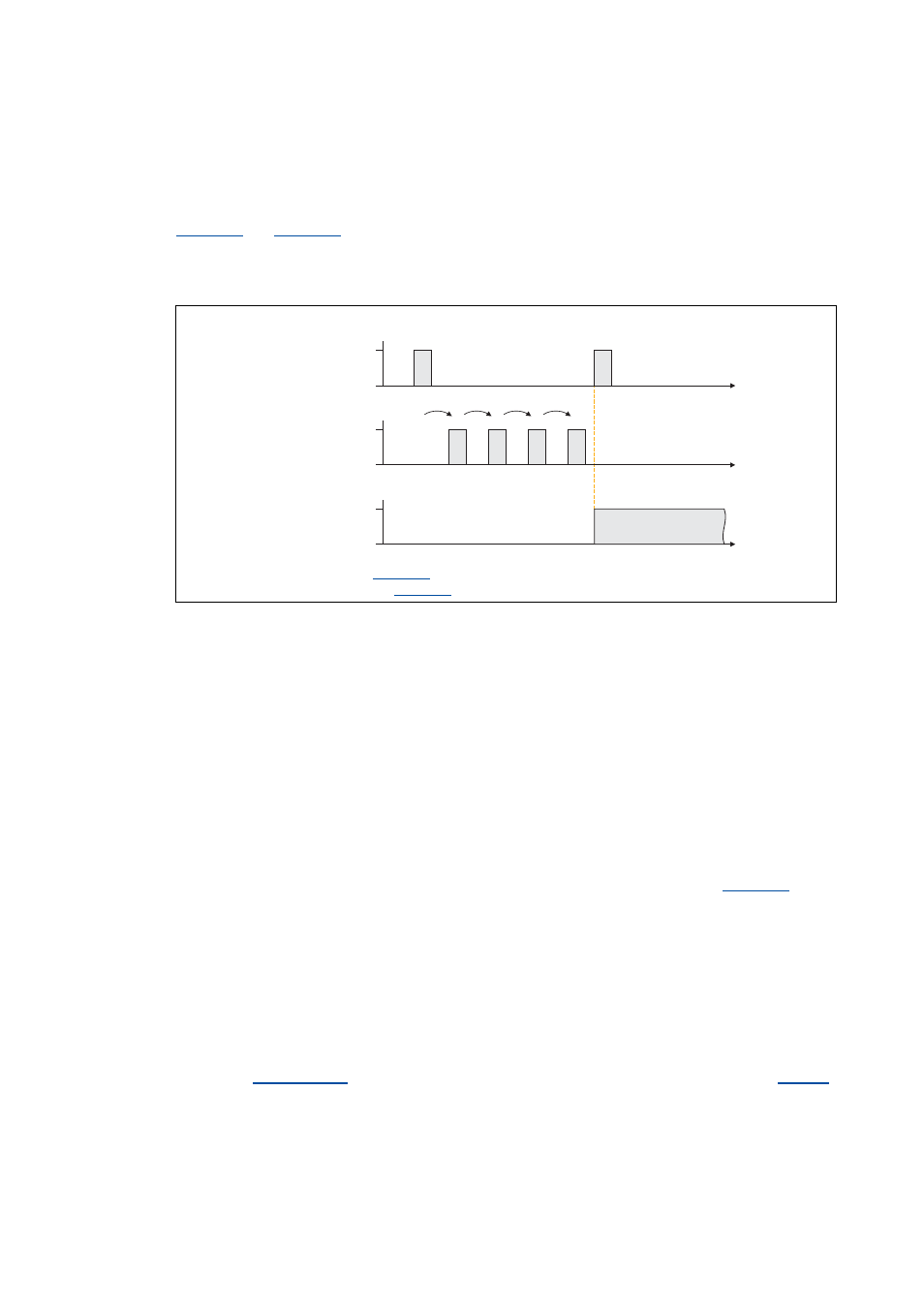
19.1.77.5 Masking out touch probe signals
When passing-through material is used, e.g. printed foil, touch probe initiators may respond several
times per cycle. For suppressing such "interference pulses", count values can be selected in
that are decremented when the touch probe pulse has been received. Only
when the counter content is "0", the synchronisation will be enabled. Please note that the settings
0 and 1 are functionally identical. If 0 or 1 is set, at least one pulse is required to activate the
synchronisation.
[19-40] Synchronisation process in the modes 1, 2, 10, 11, 12 with a masking out of the touch probe pulses
19.1.77.6 Process monitoring functions
Following error
The bFollowingErr status output is set to TRUE if the drive cannot follow its setpoint angle.
• Possible causes:
• The centrifugal mass is too high for the set acceleration or deceleration time.
• The torque limit has been reached (load torque > drive torque).
• Remedy: Unload drive or increase torque limit at the servo controller (if the power limits of the
controller have not yet been reached).
The following error is derived from the angular difference of the setpoint angle integrator minus the
actual angle integrator. The comparison value (following error limit) can be set in
.
Angle controller overflow (bPosOverflow = TRUE)
The bPosOverflow status output is set to TRUE if the angular difference that can be displayed device-
internally has been exceeded. Home positions get lost here.
Tip!
If an error response is to be triggered in case of a following error and/or angle controller
overflow, connect the corresponding status output with a free bSetError input of the
SB
and parameterise the requested error response for this input in
.
Synchronisation mode = 1, 2, 10, 11, 12
Divisor for setpoint zero pulse (
) = 0 or 1
Divisor for actual value zero pulse (
) = 4
TRUE
FALSE
bAck
t
t
TRUE
FALSE
bSetTPReceived
t
TRUE
FALSE
bActTPReceived
3
2
1
0
4
0