3 operation, 1 selecting the variables to be recorded, Selecting the variables to be recorded – Lenze 8400 TopLine User Manual
Page 737: 11 oscilloscope function
Lenze · 8400 TopLine · Reference manual · DMS 6.0 EN · 06/2014 · TD05/TD14
737
11
Oscilloscope function
11.3
Operation
_ _ _ _ _ _ _ _ _ _ _ _ _ _ _ _ _ _ _ _ _ _ _ _ _ _ _ _ _ _ _ _ _ _ _ _ _ _ _ _ _ _ _ _ _ _ _ _ _ _ _ _ _ _ _ _ _ _ _ _ _ _ _ _
11.3
Operation
This chapter describes step-by-step how to record the signal characteristics of 8400 TopLine
variables and represent, analyse, document and process them in the oscilloscope.
11.3.1
Selecting the variables to be recorded
The oscilloscope supports up to eight channels, i.e. max. eight variables can be recorded in a data
set.
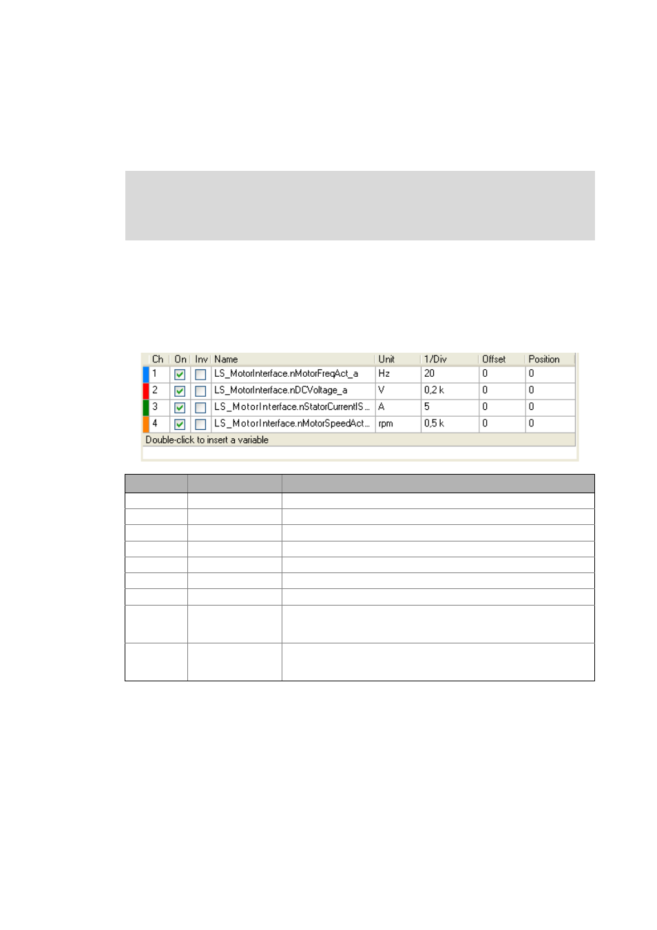
The variables to be recorded can be configured by means of the Vertical channel settings list field.
Four variables have already been selected in the default setting:
Note!
The oscilloscope can only be configured and recording can only be started when an
online connection has been established to the 8400 TopLine.
Column
Name
Meaning
1
-
Curve colour for representation in the oscillogram
2
Ch
Channel number
3
On
On/off
4
Inv
On/off inversion
5
Name
Selection of the variable to be recorded
6
Unit
Scaling
7
1/Div
Vertical scaling factor
8
Offset
Offset value
• The offset value depends on the scaling factor. It is indicated by a dashed
line in the colour of the curve on the left-hand edge of the oscillogram.
9
Position
Position value
• The position value is independent of the scaling factor. It is indicated by a
line on the left-hand edge of the oscillogram.