C01119 | ls_multiencoder: current position, C01120 | sync signal source, C01121 | sync cycle time setpoint – Lenze 8400 TopLine User Manual
Page 1165: C01119/1, C01119/2, C01121, C01120, Urce, Ed in, Selected in
Lenze · 8400 TopLine · Reference manual · DMS 6.0 EN · 06/2014 · TD05/TD14
1165
17
Parameter reference
17.2
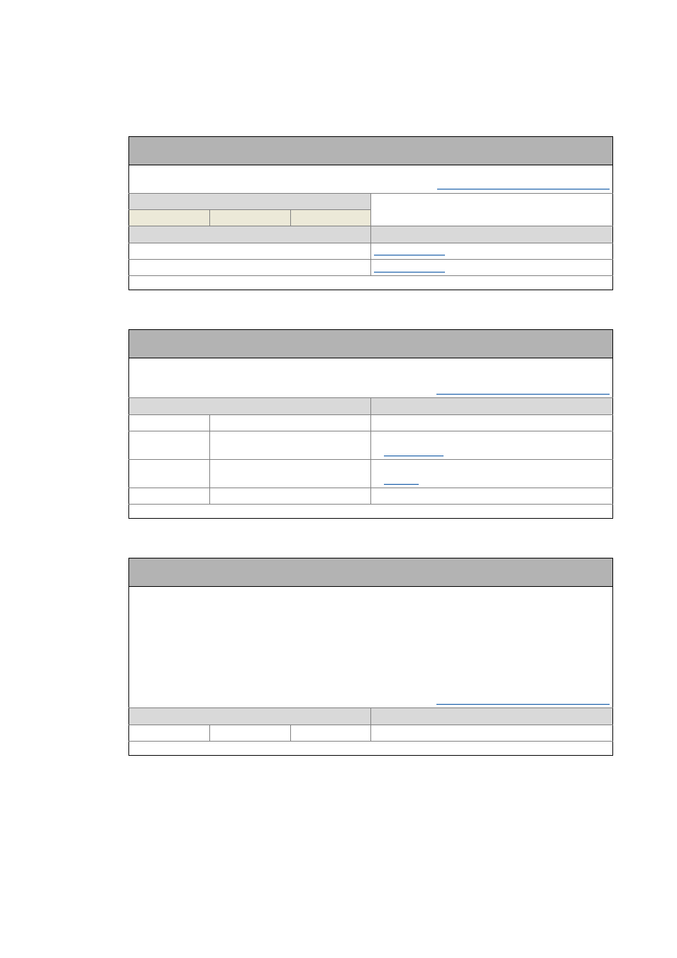
Parameter list | C01119
_ _ _ _ _ _ _ _ _ _ _ _ _ _ _ _ _ _ _ _ _ _ _ _ _ _ _ _ _ _ _ _ _ _ _ _ _ _ _ _ _ _ _ _ _ _ _ _ _ _ _ _ _ _ _ _ _ _ _ _ _ _ _ _
C01119
C01120
C01121
Parameter | Name:
C01119 | LS_MultiEncoder: Current position
Data type: INTEGER_32
Index: 23456
d
= 5BA0
h
From version 02.00.00
Encoder/feedback system: Multi-Encoder
Display range
(min. value | unit | max. value)
-214748.3647
units
214748.3647
Subcodes
Info
C01119/1
: Current position
C01119/2
: Maximum travel distance
Read access Write access CINH PLC STOP No transfer COM MOT
Scaling factor: 10000
Parameter | Name:
C01120 | Sync signal source
Data type: UNSIGNED_8
Index: 23455
d
= 5B9F
h
Selection of the signal source for device synchronisation
• The drive can only be synchronised by one source.
Synchronisation of the internal time base
Selection list
(Lenze setting printed in bold)
Info
0 Off
Synchronisation off
1 CAN on board
Synchronisation via CAN bus
2 AxisBusIO
Synchronisation via axis bus
4 MCI
Synchronisation via MCI (communication module)
Read access Write access CINH PLC STOP No transfer COM MOT
Scaling factor: 1
Parameter | Name:
C01121 | Sync cycle time setpoint
Data type: UNSIGNED_16
Index: 23454
d
= 5B9E
h
Cycle time setpoint for device synchronisation
• Time interval at which the phase control loop (PLL) in the controller expects the synchronisation signals.
• The cycle time setpoint must be set according to the cycle of the respective synchronisation source.
Note:
• Only integer multiples of 1000 μs can be set.
• Intelligent communication modules usually define the cycle time setpoint derived from the bus cycle. In this
case, a manual change is not possible.
Example: For the CAN bus, a distance of 2 ms has been set between two synchronisation signals. If the CAN bus is
to be used as synchronisation source, a synchronisation cycle of 2000 μs must be set in C01121.
Synchronisation of the internal time base
Setting range
(min. value | unit | max. value)
Lenze setting
1000
μs
20000 1000 μs
Read access Write access CINH PLC STOP No transfer COM MOT
Scaling factor: 1