6encoder/feedback system – Lenze 8400 TopLine User Manual
Page 346
6
Encoder/feedback system
6.3
Multi-Encoder (X8)
346
Lenze · 8400 TopLine · Reference manual · DMS 6.0 EN · 06/2014 · TD05/TD14
_ _ _ _ _ _ _ _ _ _ _ _ _ _ _ _ _ _ _ _ _ _ _ _ _ _ _ _ _ _ _ _ _ _ _ _ _ _ _ _ _ _ _ _ _ _ _ _ _ _ _ _ _ _ _ _ _ _ _ _ _ _ _ _
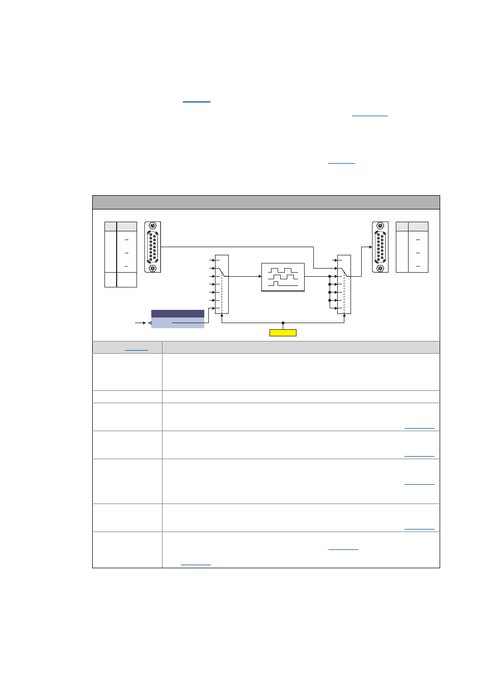
How to parameterise the master frequency output:
1. As encoder type (
), select "5: LF In/Out" to activate the master frequency output.
2. Set the number of increments for the digital frequency output in
The number of increments determines after how many output increments a zero pulse will
be generated. Each zero pulse defines a covered "revolution" of the rotary transducer
simulated by the digital frequency output.
3. Set the desired function of the digital frequency output in
(see the following
section).
Selecting the function of the digital frequency output
Function (
Info
1: Off
Digital frequency output not active
• The frequency "0" is output at the digital frequency output.
• All tracks remain on the level output last.
• After switching on the controller, the tracks A, B and Z are set to HIGH level.
2: DFIn
The TTL input signals at X8 are connected through to the digital frequency output.
3: MotorSpeed
Output of the motor encoder
• The angle of rotation derived from the motor encoder in [increments] is output as
frequency signal after being evaluated with the number of increments set in
4: LoadSpeed
Output of the load encoder
• The angle of rotation derived from the load encoder in [increments] is output as
frequency signal after being evaluated with the number of increments set in
5: Resolver
Output of the resolver angle
• The angle of rotation derived from the resolver input in [increments] is output as
frequency signal after being evaluated with the number of increments set in
• It is irrelevant for the output whether the resolver input is used as load encoder, motor
encoder or not at all within the motor control.
6: DigIn 1/2
Output of the digital inputs DI1/DI2
• The angle of rotation derived from the digital inputs in [increments] is output as
frequency signal after being evaluated with the number of increments set in
7: AFB input
Output of a speed signal of the application
• The speed signal defined via the nOut_v input of the
and output as frequency signal after being evaluated with the number of increments set
.
C00540
2
1
3
4
5
6
Off
0
Motor speed
Load speed
Resolver speed
DigIn 1/2
Off
X8
DFIn
DFOut
7
2
1
3
4
5
6
7
nOut_v
LS_DFOut
Application
Pin Signal
14
7
12
10
8
15
A
A
B
B
Z
Z
Pin Signal
1
9
3
11
5
13
A
A
B
B
Z
Z
1
8
9
15
X8
1
8
9
15
4
2
GND
V
CC