2 system blocks, 2 system blocks 8, System blocks – Lenze 8400 TopLine User Manual
Page 1698: Overview of system blocks available, 19 function library
19
Function library
19.2
System blocks
1698
Lenze · 8400 TopLine · Reference manual · DMS 6.0 EN · 06/2014 · TD05/TD14
_ _ _ _ _ _ _ _ _ _ _ _ _ _ _ _ _ _ _ _ _ _ _ _ _ _ _ _ _ _ _ _ _ _ _ _ _ _ _ _ _ _ _ _ _ _ _ _ _ _ _ _ _ _ _ _ _ _ _ _ _ _ _ _
19.2
System blocks
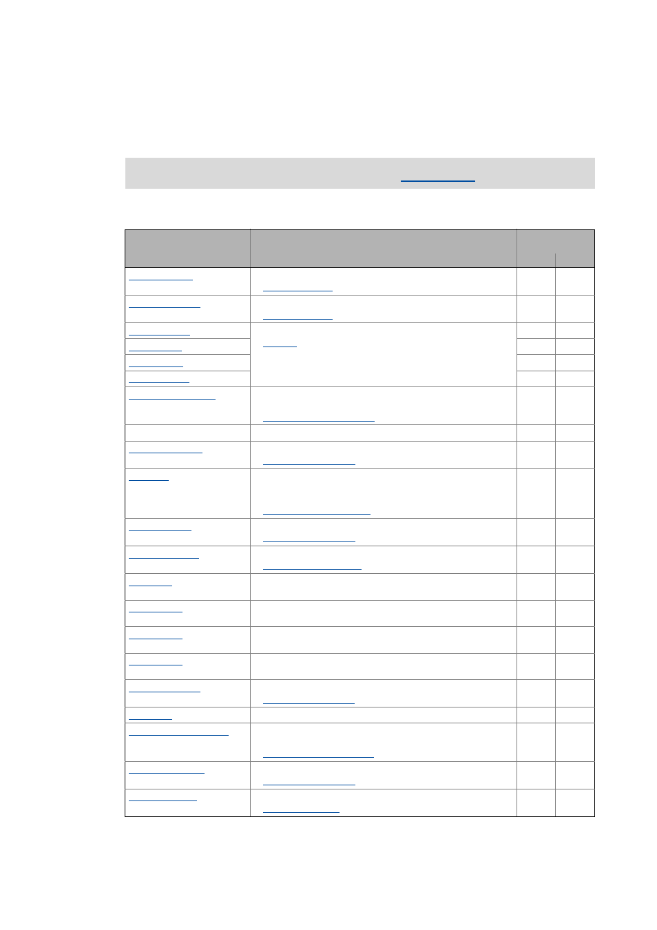
This chapter describes the system blocks which are available for the controller in the FB Editor.
Overview of system blocks available
The function blocks are described in the chapter "
System block
Function
can be inserted into
level:
I/O
Appl.
Interface to the analog input terminals
Interface to the analog output terminals
Interface to the axis bus
Control of internal functions of the CAN driver and display of the
"Operational" status as well as the node address
System bus "CAN on board" ( 749)
LS_DataAccess
Lenze internal only
Motor control status signals
Interface to the digital frequency output (multi-encoder
interface X8)
•
This SB is available from version 12.00.00.
Digital frequency coupling ( 345)
Interface to the digital input terminals
Digital input terminals ( 377)
Interface to the digital output terminals
Digital output terminals ( 398)
Display of 8 arbitrary 16-bit signals of the application on display
codes
Display of 8 arbitrary analog signals of the application on display
codes
Display of 16 arbitrary digital signals of the application on a bit
coded display code
Display of 8 arbitrary position signals of the application on
display codes
Interface to drive control (DCTRL)
Control via keypad
Interface to the basic drive function implemented in the Motion
Control Kernel (MCK)
Basic drive functions (MCK) ( 552)
Interface to motor control (MCTRL)
Interface to the Multi-Encoder