2 homing mode, Homing mode, Ant for – Lenze 8400 TopLine User Manual
Page 609: Homing modes, 9basic drive functions (mck)
Lenze · 8400 TopLine · Reference manual · DMS 6.0 EN · 06/2014 · TD05/TD14
609
9
Basic drive functions (MCK)
9.6
Homing
_ _ _ _ _ _ _ _ _ _ _ _ _ _ _ _ _ _ _ _ _ _ _ _ _ _ _ _ _ _ _ _ _ _ _ _ _ _ _ _ _ _ _ _ _ _ _ _ _ _ _ _ _ _ _ _ _ _ _ _ _ _ _ _
9.6.1.2
Homing mode
Specify the referencing mode in
, i.e. the way in which referencing is to take place.
• For reference setting, the referencing mode "100" is to be selected in
• For a reference search,
contains referencing modes "4"..."15" which can be selected
from.
Internal interfaces
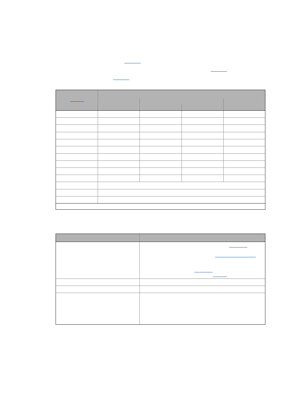
The switches/sensors are evaluated via the following internal interfaces:
Referencing mode
Evaluated signals/sensors
Touch probe sensor
(Sensor reference signal)
Travel range limit switch
Pre-stop mark at
bHomingMark
Negative limit switch
Positive limit switch
4
*
5
*
6
7
8
9
10
11
12
13
14
Positive direction of rotation to torque limit.
15
Negative direction of rotation to torque limit.
100
Set reference directly.
* From version 14.00.00
Switch/sensor
Internal interface for digital input signal
Touch probe sensor
(Sensor reference signal)
The touch probe signal source can be selected in
• If the reference signal is to follow a real touch probe, configure
the touch probe signal accordingly.
Note:
In case of setting "0: No TP" in
, the digital input DI3 is used
as signal source. An inversion of DI3 via
is considered.
Positive travel range limit switch
bLimitSwitchPos
Negative travel range limit switch
bLimitSwitchNeg
Pre-stop mark/pre-stop signal
bHomingMark
• This input has to be connected to the corresponding digital input
to which the pre-switch off sensor is connected.
• The edge sensitivity of this input and the response to the pre-
switch off signal depend on the selected homing mode (see the
following description of the homing modes).