2 set the position encoder, Set the position encoder, 3commissioning – Lenze 8400 TopLine User Manual
Page 74
3
Commissioning
3.8
Commissioning of the "Table positioning" technology application
74
Lenze · 8400 TopLine · Reference manual · DMS 6.0 EN · 06/2014 · TD05/TD14
_ _ _ _ _ _ _ _ _ _ _ _ _ _ _ _ _ _ _ _ _ _ _ _ _ _ _ _ _ _ _ _ _ _ _ _ _ _ _ _ _ _ _ _ _ _ _ _ _ _ _ _ _ _ _ _ _ _ _ _ _ _ _ _
3. After setting the machine parameters, click the Back button to change to the Overview dialog
level.
3.8.4.2
Set the position encoder
In the Lenze setting, the digital input terminals are configured as "normal" digital inputs. Since in
this system constellation DI1 and DI2 are used to connect a two-track position encoder, the function
assignment of these two inputs must be changed accordingly.
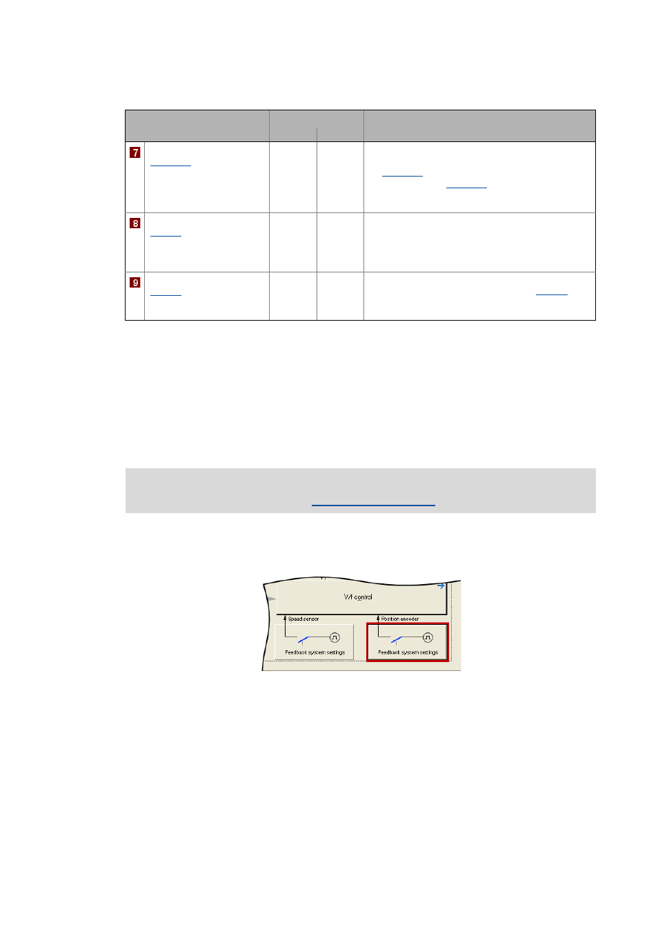
1. Go to the right side of the Application parameter tab and click the Signal flow button to change
to the Overview Signal flow dialog level.
2. Click the Feedback system settings button in the signal flow:
Axis cycle
(
0.0000 units
Cycle for Modulo measuring system
• The Modulo system is activated by setting a cycle
) > 0 units.
) is set to 0 units (Lenze
setting), the traversing range is unlimited (classical
measuring system).
Feed constant
(
)
360.0000 units/rev. The feed constant corresponds to the movement of the
machine during one revolution of the gearbox output
shaft.
• The value is entered in application units referred to
one revolution.
Reference speed
(
)
1500 rpm
All speed setpoint selections are provided in % and
always refer to the reference speed set in
The motor reference speed is indicated on the motor
nameplate.
Parameter
Lenze setting
Info
Value Unit
Detailed information on how to use a resolver/encoder as motor or position encoder can
be found in the main chapter "