142 l_sdswitchpoint - position switch points, L_sdswitchpoint, 5function blocks – Lenze E94A User Manual
Page 532
5
Function blocks
5.142
L_SdSwitchPoint - position switch points
532
Lenze · 9400 function library · Reference manual · DMS 6.7 EN · 08/2014 · TD05
_ _ _ _ _ _ _ _ _ _ _ _ _ _ _ _ _ _ _ _ _ _ _ _ _ _ _ _ _ _ _ _ _ _ _ _ _ _ _ _ _ _ _ _ _ _ _ _ _ _ _ _ _ _ _ _ _ _ _ _ _ _ _ _
5.142
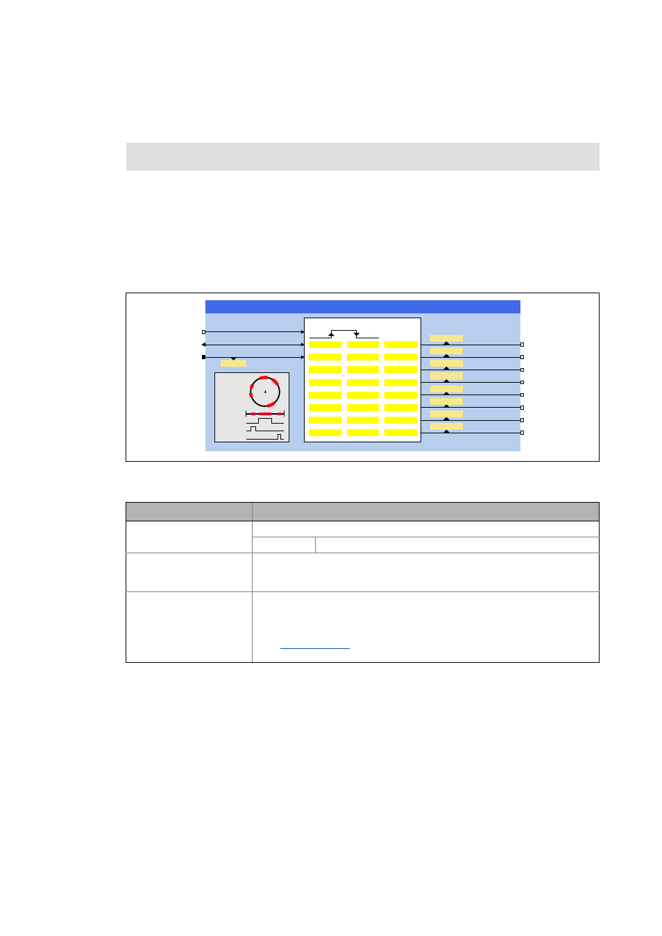
L_SdSwitchPoint - position switch points
This FB serves to implement up to 8 simple position switch points (cams). When the current drive
position is inside a range defined via parameters, the output assigned to this "switching area" is set
to TRUE.
• The output setting does not depend on whether the switching range is approached by the posi-
tive or negative side.
• In the modulo measuring system (rotary table) the switching ranges can also be defined beyond
the 0° position (e.g. switching on at 350° and off at 10° in CW rotation).
Inputs
Function library:
LenzeServoDrive
Runtime software licence:
Motion Control HighLevel
Motion Control TopLevel
Identifier/data type
Information/possible settings
bEnable
BOOL
Enable FB
TRUE Position switch points are activated.
dnPosIn_p
DINT
Input for accepting the current position
• Connect this input with the position signal to be accepted. Depending on the ap-
plication, this can be a setpoint or an actual position.
AxisData
Machine parameters
• For accepting the machine parameters of the drive/motor, connect this input
with the output DI_AxisData of the SB LS_DriveInterface.
• The machine parameters of a master drive can be displayed with the
FB
. In this case, the FB output AxisData must be connected to
this input.
/B6G6ZLWFK3RLQW
E(QDEOH
GQ3RV,QBS
$[LV'DWD
E6ZLWFK
E6ZLWFK
E6ZLWFK
E6ZLWFK
E6ZLWFK
E6ZLWFK
E6ZLWFK
E6ZLWFK
&
&
&
&
&
&
&
&
&
&
&
&
&
&
&
&
&
&
&
&
&
&
&
&
(QDEOH
RXWSXW
6ZLWFKLQJ
SRLQW
7ULSSLQJ
SRLQW
&
&
&
&
&
&
&
&
URWDU\D[LV
OLQHDUD[LV
& 3RVLWLRQXQLW