1 typical application, 5function blocks – Lenze E94A User Manual
Page 330
5
Function blocks
5.91
L_LdMarkSync - mark synchronisation
330
Lenze · 9400 function library · Reference manual · DMS 6.7 EN · 08/2014 · TD05
_ _ _ _ _ _ _ _ _ _ _ _ _ _ _ _ _ _ _ _ _ _ _ _ _ _ _ _ _ _ _ _ _ _ _ _ _ _ _ _ _ _ _ _ _ _ _ _ _ _ _ _ _ _ _ _ _ _ _ _ _ _ _ _
5.91.1
Typical application
Many synchronous operations require a slave drive (tool) to move in synchronism with a master si-
gnal/master drive. This motion can be corrected using additional sensor technology.
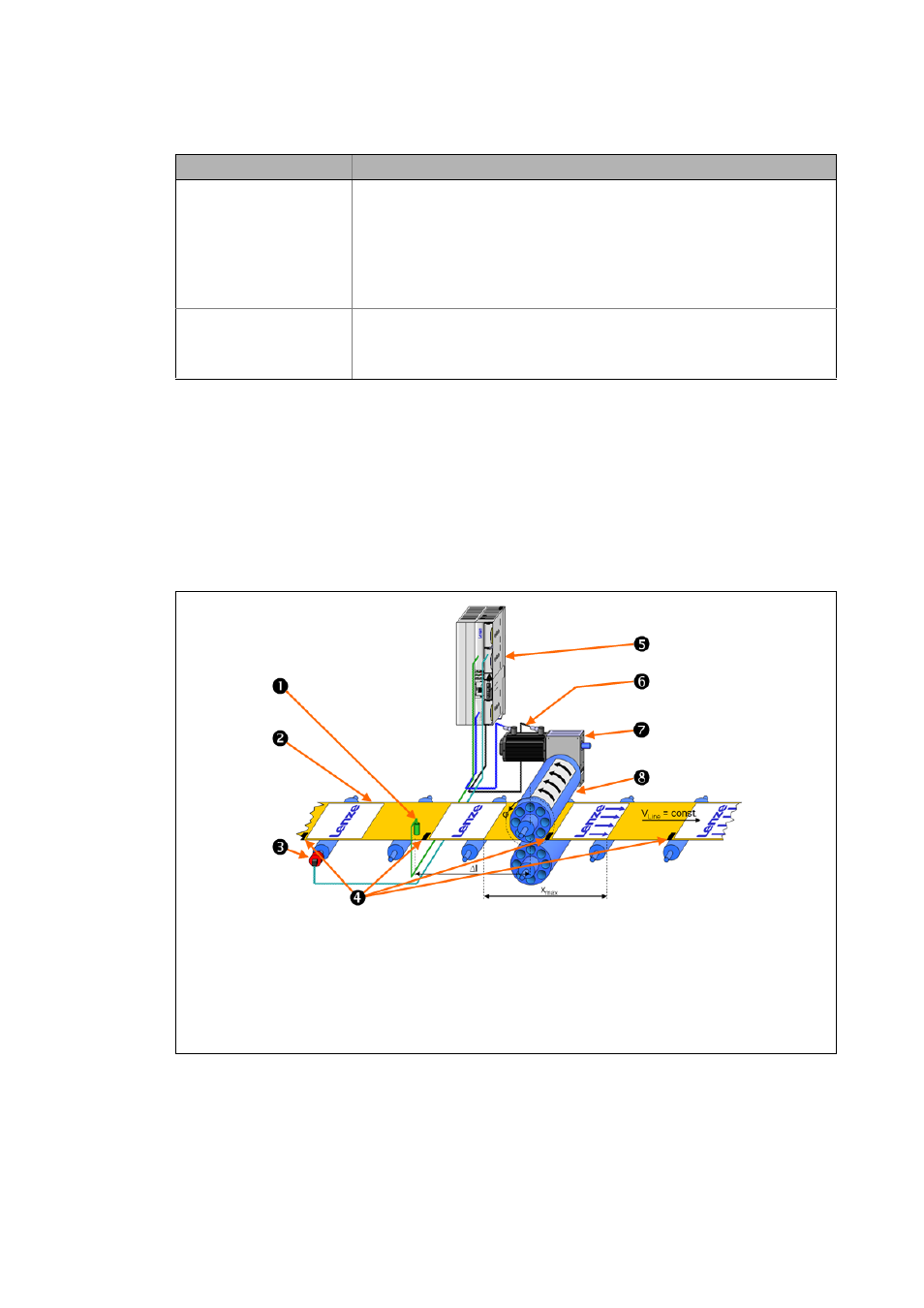
In the following example, a print register has already been defined by print marks on the web. High-
precision detection of these print marks in the controller is possible via fast digital inputs (touch pro-
be inputs).
[5-48] Example: Printing roller drive including print-mark correction
dnTpTpDistance_p
DINT
Distance between the two touch probes last detected in [increments]
• May e.g. serve to determine the print register (distance between two print
marks).
• Please make sure that the touch probe sensor is positioned in such a way that no
cycle without touch probe detection is possible between two detected touch pro-
bes. In this case, the output would indicate a distance which is one cycle too short.
This can be prevented by positioning the touch probe sensor in the middle of the
cycle.
dnTpPos_p
DINT
Detected TP position in [inc]
(Actual TP position at which the current touch probe has been detected.)
• The distance to the TP setpoint position is calculated using the actual TP position
that is output here: dnTpDifference_p = dnTpSetPos_p - dnTpPos_p
Identifier/data type
Value/meaning
Print-mark sensor
Web including print register 0 ... x
max
(print image: "Lenze")
Master value encoder
Print marks
9400 controller (slave drive = printing roller)
Printing roller drive motor including feedback system
Gearbox (slave drive)
Printing roller including block (print image: "Arrows")