5function blocks – Lenze E94A User Manual
Page 375
Lenze · 9400 function library · Reference manual · DMS 6.7 EN · 08/2014 · TD05
375
5
Function blocks
5.99
L_LdVirtualMasterP - virtual master for synchronism
_ _ _ _ _ _ _ _ _ _ _ _ _ _ _ _ _ _ _ _ _ _ _ _ _ _ _ _ _ _ _ _ _ _ _ _ _ _ _ _ _ _ _ _ _ _ _ _ _ _ _ _ _ _ _ _ _ _ _ _ _ _ _ _
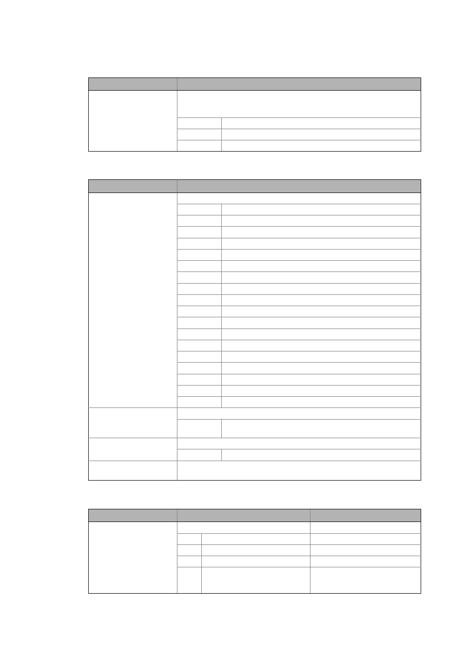
Outputs
Parameter
dwOperatingMode
DWORD
From library V02.07.xx.xx
Selection of the operating mode via process date
• This input is only active if the operating mode "3: Speed and mode via input" has
been selected in C05010.
0 Continuous operation
1 Inching
2 Handwheel function
Identifier/data type
Value/meaning
dnState
DINT
Status (bit coded)
Bit 1 State active
Bit 2 Procedure completed
Bit 3 Acceleration/deceleration phase
Bit 5 Counter-clockwise rotation
Bit 10 Zero crossing active
Bit 15 Error
bit16 Starting position is beyond the cycle
bits17 Error in the master signal (position or speed)
Bit 18 No cycle available
Bit 19 Maximum speed = "0"
bits23 No valid axis data structure
Bit 24 Single cycle
bits25 Automatic mode
Bit 26 Stopping is active
Bit 27 Manual jog
Bit 28 Internal setpoint speed is active
Bit 29 Position difference - external master
bits30 Electronic handwheel is active
bInTarget
BOOL
Status signal "Master shaft has reached stop position"
TRUE Master shaft dnPosOut_p has reached the stop position set in
C05011.
bBusy
BOOL
Status signal "master shaft is positioned"
TRUE Master shaft dnPosOut_p is positioned.
dnPosOut_p
DINT
Master position output (current position of the master shaft in the cycle) in [inc]
• C05027 indicates the master position in the real unit of the machine.
Parameter
Possible settings
Info
C05010
VMaster: Operating mode
0 Continuous operation
Lenze setting
1 Inching
2 Handwheel function
3 Selection of speed and mode via
input
Master speed 1 and the operating
mode are selected via the
corresponding inputs of the FB.
Identifier/data type
Information/possible settings