5function blocks – Lenze E94A User Manual
Page 329
Lenze · 9400 function library · Reference manual · DMS 6.7 EN · 08/2014 · TD05
329
5
Function blocks
5.91
L_LdMarkSync - mark synchronisation
_ _ _ _ _ _ _ _ _ _ _ _ _ _ _ _ _ _ _ _ _ _ _ _ _ _ _ _ _ _ _ _ _ _ _ _ _ _ _ _ _ _ _ _ _ _ _ _ _ _ _ _ _ _ _ _ _ _ _ _ _ _ _ _
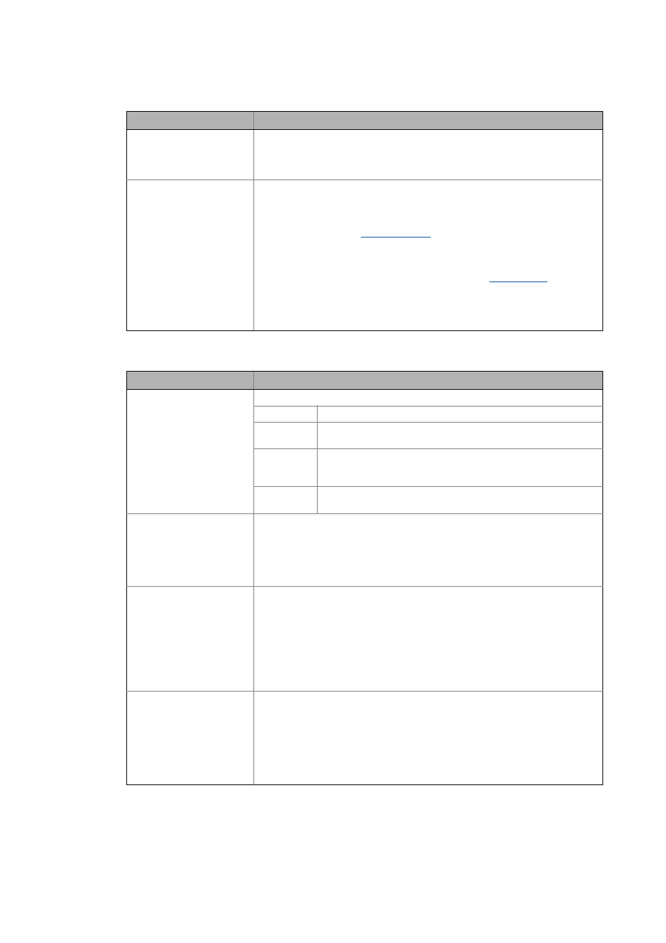
Outputs
dnTpSetPos_p
DINT
Touch probe setpoint position in [inc]
• At this input, specify the position at which the touch probe ideally occurs.
• If the touch probe is detected at its (ideal) TP setpoint position, a correcting mo-
tion is not required (TP difference dnTpDifference_p = 0).
AxisData
Specification of the measuring system which is used to evaluate the touch probe
event.
The following sources can be used for this input:
• If the master position is corrected (x touch probe), an arbitrary measuring system
can be defined via the
FB. In this case, its AxisData output must
be connected to this input.
• If an axis position is corrected (y touch probe), the DI_AxisData output of the
LS_DriveInterface SB must be connected to this input.
• Some of the cam technology function blocks (e.g. the
FB) output
the measuring systems defined via »Cam Designer«. In this case, the correspon-
ding measuring system output must be connected to this input.
Note:
The connected measuring system must be a modulo measuring system.
Identifier/data type
Value/meaning
dnState
DINT
Status
Bit15 Group error (see bit 16 ... 31)
bits18 The specified modulo measuring system (the AxisData input) does
not have a valid cycle (cycle = 0).
bits20 The TP setpoint position at the dnTpSetPos_p input is outside of the
permissible cycle of the modulo measuring system (the AxisData in-
put).
bits23 Error in the measuring system: The pointer at the AxisData input
does not refer to a valid axis data structure.
dnPosOffset_p
DINT
Aggregated position offset in [increments]
(Aggregation of all correcting motions performed so far)
• This output outputs an unlimited correction position.
• If the TP is corrected at the axis side (y touch probe), the output can directly be
connected to the FDB_dnPosOffset_p input of the LS_Feedback SB when the axis
needs to be corrected.
dnActDifference_p
DINT
Remaining position difference in [increments]
• If a touch probe is detected via the bTpReceived input, this output is set to the de-
tected TP deviation, dnTpDifference_p.
• Then, the remaining TP deviation is compensated to zero via the
dnMakeUpLeeway_s input if a correcting motion is reported (correction distance
monitoring).
• The shorter distance to the TP setpoint position is always output.
(Caution: The function block requires a modulo measuring system to work cor-
rectly!)
dnTpDifference_p
DINT
Last TP deviation in [inc]
(TP deviation between the TP setpoint position, dnTpSetPos_p, and the actual positi-
on, dnTpPos_p, at which the touch probe has been detected.)
• If a touch probe is detected via the bTpReceived input, the dnActDifference_p out-
put is set to this value additionally.
• The shorter distance to the TP setpoint position is always output.
(Caution: The function block requires a modulo measuring system to work cor-
rectly!)
Identifier/data type
Information/possible settings