5function blocks – Lenze E94A User Manual
Page 334
5
Function blocks
5.91
L_LdMarkSync - mark synchronisation
334
Lenze · 9400 function library · Reference manual · DMS 6.7 EN · 08/2014 · TD05
_ _ _ _ _ _ _ _ _ _ _ _ _ _ _ _ _ _ _ _ _ _ _ _ _ _ _ _ _ _ _ _ _ _ _ _ _ _ _ _ _ _ _ _ _ _ _ _ _ _ _ _ _ _ _ _ _ _ _ _ _ _ _ _
Operating mode
The core function of the interconnection is contained in the FB
: On the basis of the
current x position (integrator output L_SdIntegrateAxis1.dnPosOut_p) and the set position of the
print-mark signal x
TP
(output L_SdSetPosition6.dnPosOut_p) the FB detects the correction distance
Δx
TP
when a print mark pulse is detected.
In the example, the print-mark sensor is connected to the digital input DI8, touch probe is therefore
detected via the LS_TouchProbe8 system block.
The correction distance Δx
TP
is led from the signal output L_LdMarkSync2.dnActDifference_p to the
profile generator
which generates a correction profile V
x,comp
.
The correction speed V
x,comp
is superimposed on the real master speed (system variable
DFIN_dnActualSpeed_s) via the FB
and then integrated in the integrator block
modulo to a master position 0 ... x
max
.
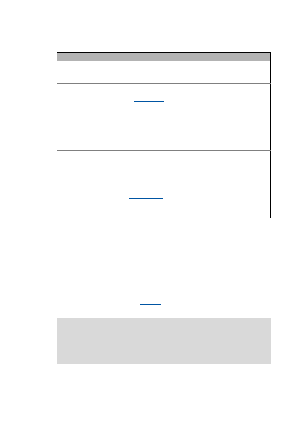
Function block
Function
L_LdPosCtrlLin4
Time-controlled profile generation
• Using the detected deviation (print-mark correction path), the
generates a time-controlled speed setpoint.
• The speed setpoint is provided at the L_LdPosCtrlLin4.dnSpeedOut_s output.
LS_TouchProbe8
Detection of the print-mark signal
L_SdSetPosition6
Selection of the set position of the print-mark sensor
• The FB
converts the set position defined in the application unit
[unit] into an incremental value.
• The reference measuring system is the master measuring system which is defi-
L_LdMarkSync2
Detection of the correction distance Δx
TP
• The FB
detects the correction distance Δx
TP
based on the current x
position and the set position of the print mark signal x
TP
if a print mark pulse is
detected via the SB LS_TouchProbe8.
• The correction distance Δx
TP
is provided at the L_LdMarkSync2.dnActDifference_p
output.
L_SdSetAxisData1
Definition of the master measuring system
• Using the
FB, machine parameters of a higher-level drive can be
displayed.
LS_DigitalFrequencyInput
Detection of the digital frequency and output as speed signal
L_TbSub1
Injection of the correction speed
• The
FB performs a subtraction without limitation.
L_SdIntegrateAxis1
Integration of the resulting speed signal to a master position (x position)
• The
FB integrates a speed into a position.
L_LdLinearCoupling1
Synchronous function
• The FB
establishes the coupling between master and axis
measuring system.
Note!
Touch probe corrections cannot be applied to absolute master positions, as for instance
if selected via MotionBus.
A touch probe correction on the master value side requires a master speed as master va-
lue selection (e.g. via digital frequency coupling).