5function blocks – Lenze E94A User Manual
Page 190
5
Function blocks
5.11
L_CamSyncIn - synchronous/oversynchronous clutch-in
190
Lenze · 9400 function library · Reference manual · DMS 6.7 EN · 08/2014 · TD05
_ _ _ _ _ _ _ _ _ _ _ _ _ _ _ _ _ _ _ _ _ _ _ _ _ _ _ _ _ _ _ _ _ _ _ _ _ _ _ _ _ _ _ _ _ _ _ _ _ _ _ _ _ _ _ _ _ _ _ _ _ _ _ _
Motion sequence
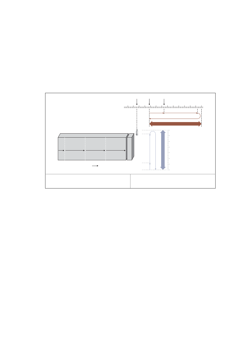
The motion sequence of the flying saw drive consists of the following phases:
A. Synchronising: First the tool must be accelerated from the basic position to the material speed.
When the material speed has been reached, the tool must be in the cutting position. The exact
position of the points of intersection on the web is detected by a touch probe sensor.
B. Synchronous travel: The tool immerses into the material, then moves in synchronism with the
material speed until the machining process is terminated including the lifting of the tool.
C. Travel back to initial position: Finally the tool is repositioned to the basic position, e.g. with the
LS_Positioner system block.
[5-25] Phases and positions in the motion sequence of a "flying saw""
Synchronisation processes
In this example, always three movements are to be synchronised:
1. Running material to web (master value/master position).
2. Synchronising the slide with saw to web.
3. Releasing the cut with the saw.
Thus, three different measuring systems must be related to each other. In a path-controlled system,
synchronising and the release of the cut can be started simultaneously, since the master value/mas-
ter position ensure that both synchronisation processes are terminated at the same time. This, ho-
wever, does not apply to the traverse path with different master speeds.
Position of the touch probe sensor
Starting position (basic tool position)
Starting position - synchronous range
Synchronising
Synchronous travel
Travel back to initital position
TP
dnTpPos_p
dnOpenPos_p
dnSyncPos_p
0
0
2
1
0
1
2
0
v
Traversing range - axis 1
T
raversing
range
-
axis
2