117 l_sddelaycomp - dead time compensation, L_sddelaycomp, 5function blocks – Lenze E94A User Manual
Page 453
Lenze · 9400 function library · Reference manual · DMS 6.7 EN · 08/2014 · TD05
453
5
Function blocks
5.117
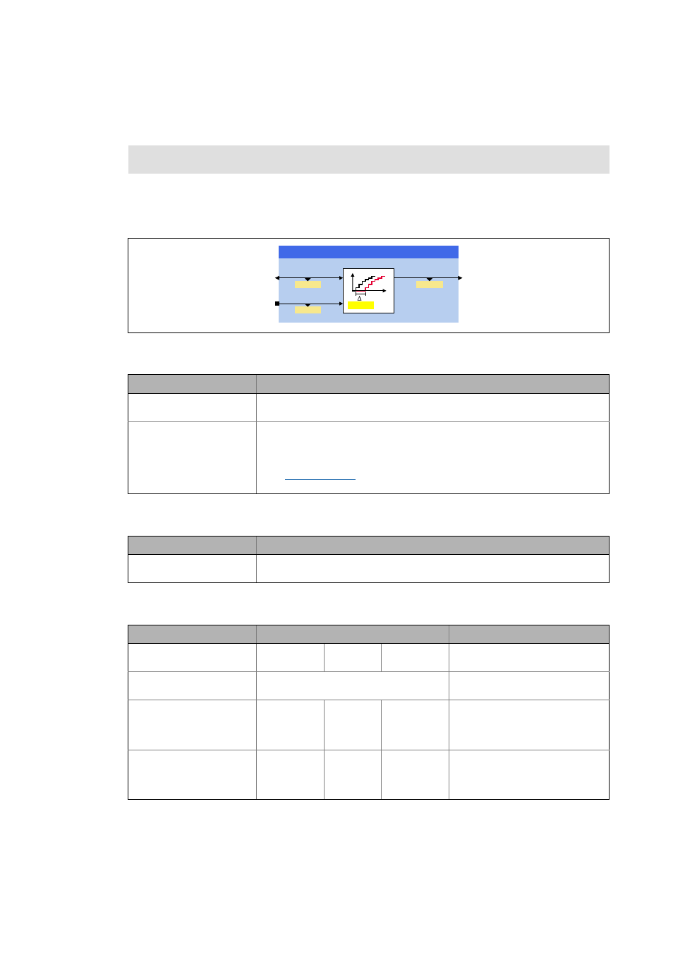
L_SdDelayComp - dead time compensation
_ _ _ _ _ _ _ _ _ _ _ _ _ _ _ _ _ _ _ _ _ _ _ _ _ _ _ _ _ _ _ _ _ _ _ _ _ _ _ _ _ _ _ _ _ _ _ _ _ _ _ _ _ _ _ _ _ _ _ _ _ _ _ _
5.117
L_SdDelayComp - dead time compensation
This FB extrapolates a signal by a set time. In this way, the FB can compensate for the dead times of
incoming signals resulting from the bus transfer.
• The FB considers a modulo measuring system and the cycle of the selected machine parameters.
Inputs
Outputs
Parameter
Function library:
LenzeServoDrive
Runtime software licence:
Motion Control HighLevel
Motion Control TopLevel
Identifier/data type
Information/possible settings
dnPosIn_p
DINT
Position in [inc]
AxisData
Machine parameters
• For accepting the machine parameters of the drive/motor, connect this input
with the output DI_AxisData of the SB LS_DriveInterface.
• The machine parameters of a master drive can be displayed with the
FB
. In this case, the FB output AxisData must be connected to
this input.
Identifier/data type
Value/meaning
dnPosOut_p
DINT
Compensated position in [inc]
Parameter
Possible settings
Information
C04320
-100.000
ms
100.000 Rate time
• Initialisation: 0.000 ms
C04321
As of library V02.02.xx.xx
String of digits
Position unit
• Read only
C04322
As of library V02.02.xx.xx
-214000.0000
Unit
214000.0000 Position at the input
• Display of the dnPosIn_p input si-
gnal in the real unit of the machi-
ne.
C04323
As of library V02.02.xx.xx
-214000.0000
Unit
214000.0000 Position at the output
• Display of the dnPosOut_p output
signal in the real unit of the ma-
chine.
GQ3RV2XWBS
GQ3RV,QBS
/B6G'HOD\&RPS
$[LV'DWD
2XW
,Q
&
W
&
&
& 8QLW