5function blocks – Lenze E94A User Manual
Page 331
Lenze · 9400 function library · Reference manual · DMS 6.7 EN · 08/2014 · TD05
331
5
Function blocks
5.91
L_LdMarkSync - mark synchronisation
_ _ _ _ _ _ _ _ _ _ _ _ _ _ _ _ _ _ _ _ _ _ _ _ _ _ _ _ _ _ _ _ _ _ _ _ _ _ _ _ _ _ _ _ _ _ _ _ _ _ _ _ _ _ _ _ _ _ _ _ _ _ _ _
Synchronisation to print marks
The "Arrows" print image is to be printed properly on to the "Lenze" print image on the web. For this
purpose and in addition to the material speed signal (master value encoder), the printing roller drive
receives a pulse from the print-mark sensor which is connected to one of the digital inputs of the
controller.
If the distance Δl between the print-mark sensor and the twelve o'clock position ("kiss point") of the
printing roller is known, the printing roller drive is able to correct the motion of the printing roller
so that the "Arrows" print image is printed exactly at the required position on the web when the
print-mark pulse is detected.
Since the production process in the example is periodical, one print-mark pulse appears per cycle.
Ideally, the pulse always appears at a certain set position x
TP
in the modulo cycle 0 ... x
max
. If the
print mark pulse is detected at another position than at its set position x
TP
, there is a deviation Δx
TP
between setpoint and actual position of the print mark pulse.
Tip!
Controlled compensation can be used to achieve "smooth" mark synchronisation to avoid
delta pulses when correcting print marks.
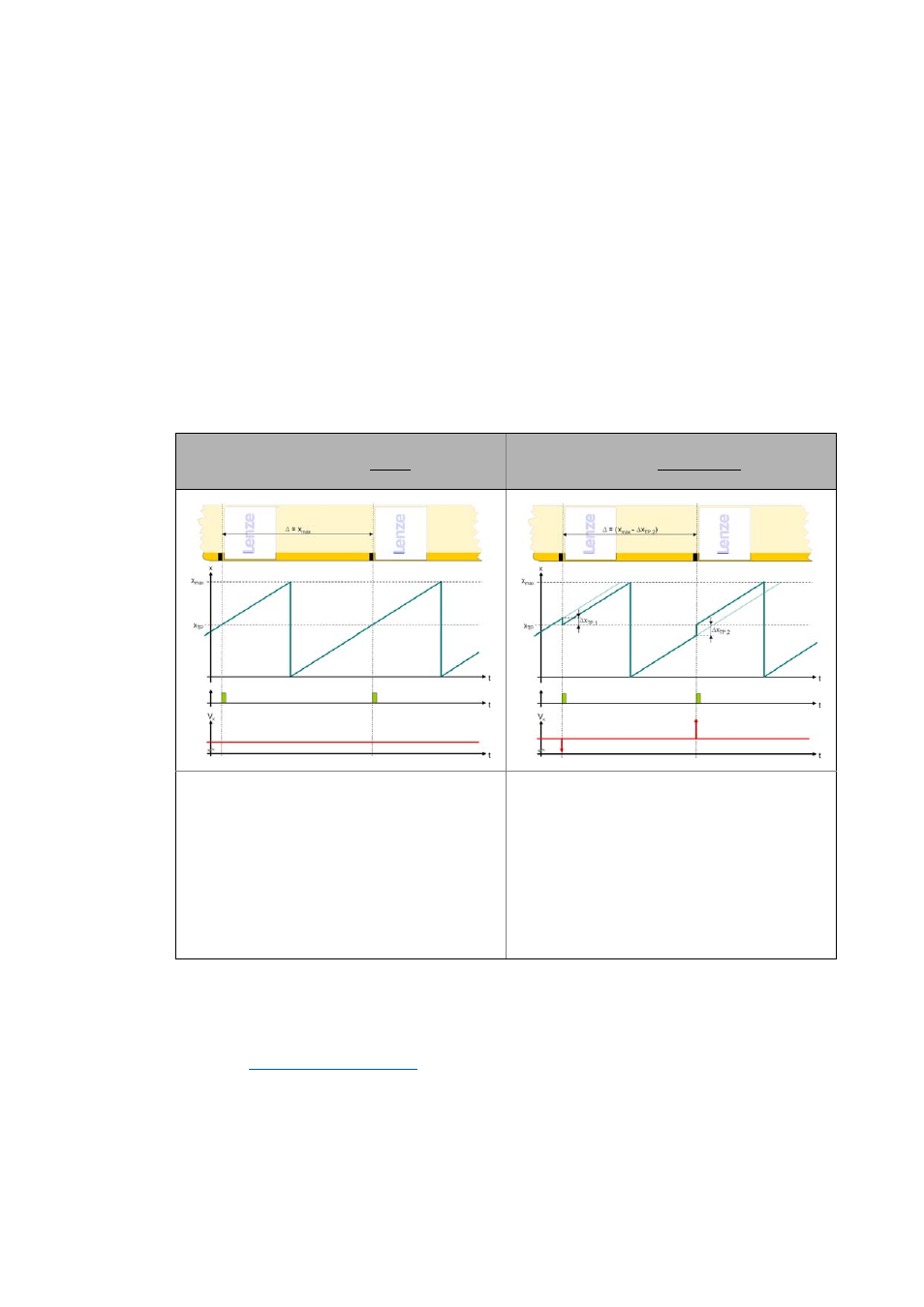
Signal characteristic 1:
Print-mark pulses always appear exactly periodically
with a distance of x
max
.
Signal characteristic 2:
Print-mark pulses appear approximately periodically
(difference Δx
TP
to x
max
).
The touch probe signal is always detected at position
x = x
TP
in the modulo cycle 0 ... x
max
.
In this case, position value x need not be corrected and
shows an ideal saw-tooth profile if speed V
x
is constant.
If the touch probe signals appear irregularly, the conti-
nuous modulo position x has not reached setpoint posi-
tion x
TP
yet, or is already past it. However, since the touch
probe signal is always assigned to a defined setpoint po-
sition x
TP
, position value x needs to be corrected accor-
dingly:
In the simplest case, position value x can be set to set-
point position x
TP
if touch probe signal "hard" is detec-
ted.
Thus, speed V
x
shows corresponding discontinuities (del-
ta pulses) at the times when the touch probe signals are
detected.