Characteristic, C 84), 9400 highline | parameter setting & configuration – Lenze E94AxHE Servo Drives 9400 HighLine (Firmware 01-37) User Manual
Page 84
9400 HighLine | Parameter setting & configuration
Motor interface
Initial commissioning | Optimise current controller
84
Firmware 1.37 - 09/2006
L
5.1.11.2
Example for determining the saturation characteristic
Given values:
r
Rated motor current: 5 A
r
Maximum motor current: 20 A
r
Maximum process current: 15 A (must be set later in
)
Procedure:
= "off").
2. Set the maximum current up to which the motor is to be operated in the process in
– The value set in
.
3. Adjust the current controller with different current setpoints and note the
corresponding settings for Vp and Tn.
– The procedure for the adjustment is described in the chapter "
".
– The current setpoints that are to be set for the prevailing adjustment in
result from the scaling of the maximum process current to the X axis of the
saturation characteristic.
– Which points are required to display the saturation characteristic with a sufficient
quality, varies from motor to motor and must therefore be detected individually.
– For this example currents have been selected which are situated on the grid points
5, 9, 13 and 15 a measurement has been carried out at rated motor current:
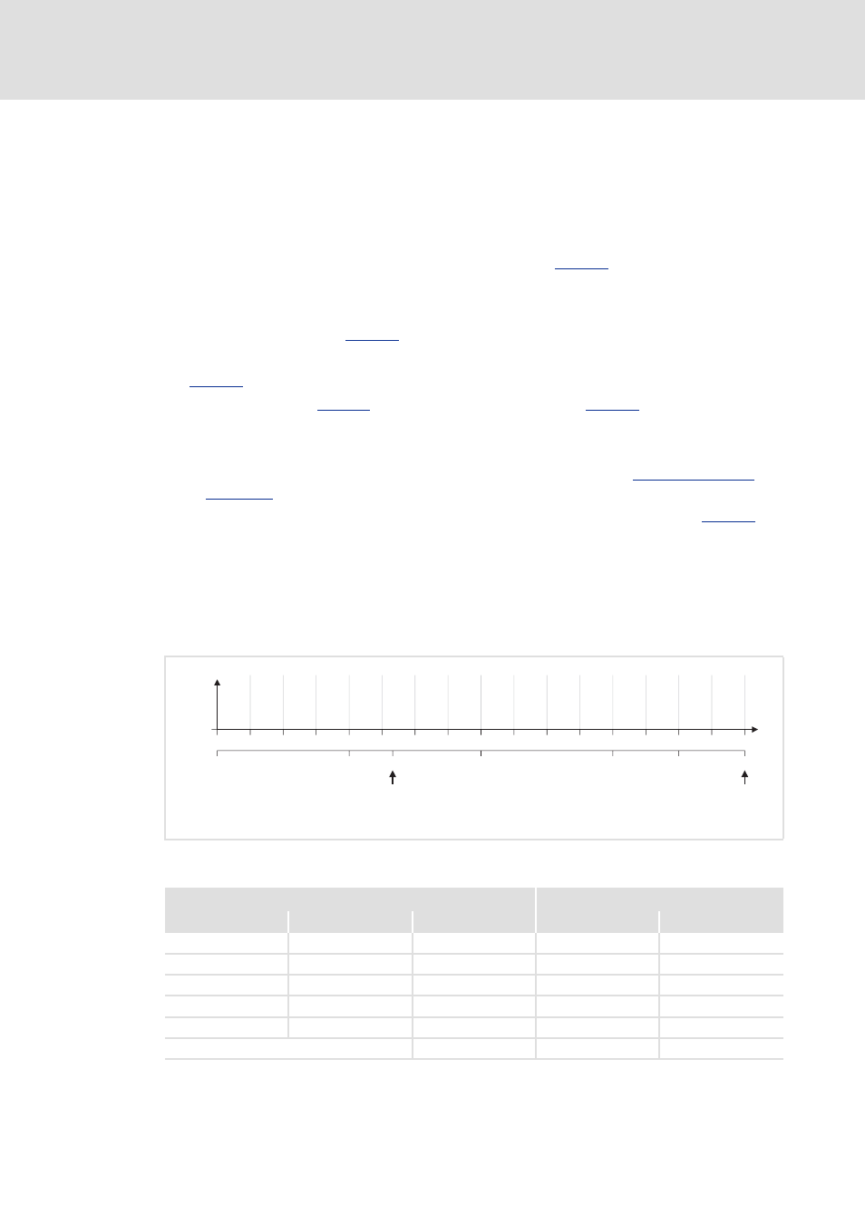
[5-3]
Saturation characteristic: Distribution of the grid points
n
Rated motor current
o
Maximum process current (≡ 100 %)
15 A
2
3
4
5
6
7
8
9
10
11
12
13
14
15
16
17
7.5 A
3.75 A
11.25 A
12.38 A
5 A
0
6.25
12.5
18.75
25
31.25
37.5
43.75
50
56.25
62.5
68.75
75
81.25
87.5
93.75
100
0 A
I
max
[%]
Vp
Tn
[V/A]
[ms]
1
Specifications for adjustment
Measured values
Grid point
Scaling
Setting C00022
Vp [V/A]
Tn [ms]
5
0.25 * 15 A =
3.75 A
13
6.5
9
0.5 * 15 A =
7.5 A
8
4
13
0.75 * 15 A =
11.25 A
5
2.5
15
0.875 * 15 A =
12.38 A
4
2
17
1.0 * 15 A =
15 A
3
1.7
Rated motor current =
5 A
10
5