2 hardware limit positions (limit switch), Hardware limit positions (limit switch), C 204) – Lenze E94AxHE Servo Drives 9400 HighLine (Firmware 01-37) User Manual
Page 204: 9400 highline | parameter setting & configuration
9400 HighLine | Parameter setting & configuration
Basic drive functions
Limiter | Parameter setting
204
Firmware 1.37 - 09/2006
L
9.10.1.2
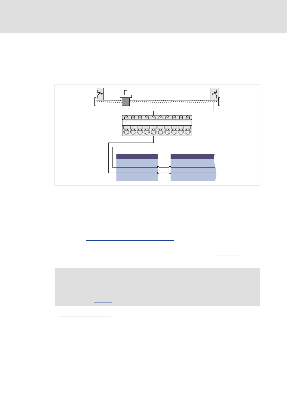
Hardware limit positions (limit switch)
The travel range limits are monitored via limit switch inputs LIM_bLimitSwitchPositive and
LIM_bLimitSwitchNegative of the SB LS_Limiter.
Both inputs react to the TRUE status and must be connected to the corresponding digital
inputs which are connected with the limit switches.
[9-6]
Example: Connection of the travel range limit switches to the digital inputs 3 & 4
r
If the limit switch is activated, the drive axis is stopped automatically and a changeover
via the function state "Drive is stopped" to the function state "Error" is effected.
r
An error is caused via an internal system interface and entered in to the logbook of the
controller. The drive can only be traversed again when the error is acknowledged.
r
An activated limit switch can be retracted using the function "Retracting the limit
switch".
Retracting of an activated limit switch
r
When the limit switches are connected to the distributed terminals, both inputs
LIM_bLimitSwitchPositive and LIM_bLimitSwitchNegative of the SB
can be
connected via a bus system (e.g. system bus) with the distributed terminal.
See also:
X5
GI
RFR
DI1
DI2
DI3
DI4
DI5
DI6
DI7
DI8
LS_DigitalInput
DIGIN_bIn4
DIGIN_bIn3
LS_Limiter
LIM_bLimitSwitchPositive
LIM_bLimitSwitchNegative
Note!
If digital inputs for connecting the limit switch are to be fail-safe (activation at
LOW level), simply change the terminal polarity of the corresponding digital
inputs in