2 actual value and status signals, 9400 highline | parameter setting & configuration – Lenze E94AxHE Servo Drives 9400 HighLine (Firmware 01-37) User Manual
Page 300
9400 HighLine | Parameter setting & configuration
TAs for interconnection via electrical shaft
TA "Electronic gearbox" | Assignment of the I/O terminals
300
Firmware 1.37 - 09/2006
L
12.2.2.2
Actual value and status signals
The following tables contain the Lenze assignment of the analog and digital outputs for
the technology application "Electronic gearbox".
r
The default signal configuration if required can be easily changed by parameterising
the multiplexer parameters assigned.
Analog outputs
Digital outputs
State bus
Display elements
Terminal X3
Signal (Lenze setting)
Signal configuration
AO1
Motor speed
• Scaling: ±10 V ≡ motor reference speed (
)
C03110/1
AO2
Motor torque (setpoint)
• Scaling: ±10 V ≡ Motor reference torque (
C03110/2
I/O terminals Analog outputs (C 120)
Terminal X4
Signal (Lenze setting)
Signal configuration
DO1
Status "Drive ready"
• This operating state is active if the controller is enabled by setting
the digital input RFR to HIGH level and no error has occurred.
C03100/1
DO2
Status "Electrical shaft enabled"
C03100/2
DO3
Status "Limitation active"
• A setpoint is limited at the moment.
C03100/3
DO4
"Error" status
• If the controller is in the error state, the digital output DO4 is set
to HIGH level.
C03100/4
I/O terminals Digital outputs (C 125)
Terminal X2
Signal (Lenze setting)
Signal configuration
SB
"Application error" status
• The state bus is put in the "error" status.
C03100/5
I/O terminals Monitoring function "State bus" (C 127)
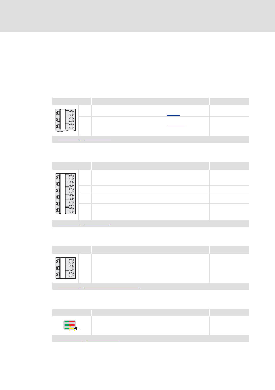
User LED
Signal (Lenze setting)
Signal configuration
Status "Electrical shaft enabled"
C03100/6
Drive interface LED status displays (C 34)
GA
AO1
AO2
GO
24O
DO1
DO2
DO3
DO4
GE
24E
SB