1 master axis (master shaft), 9400 highline | parameter setting & configuration – Lenze E94AxHE Servo Drives 9400 HighLine (Firmware 01-37) User Manual
Page 338
9400 HighLine | Parameter setting & configuration
TAs for interconnection via electrical shaft
TA "Synchronism with mark synchronisation" | Machine parameters
338
Firmware 1.37 - 09/2006
L
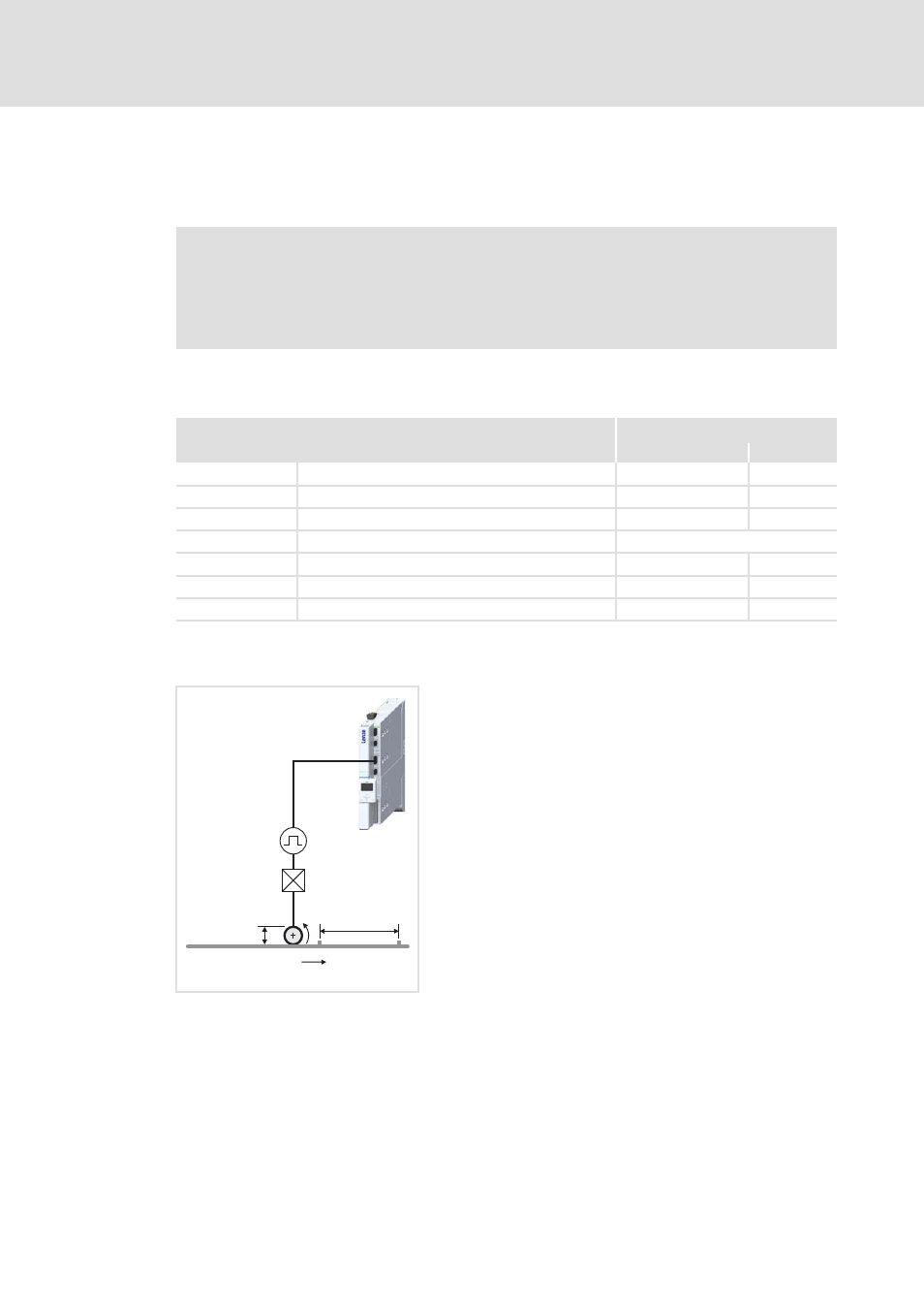
12.3.3.1
Master axis (master shaft)
For scaling and imaging the master value in the application, the machine parameters of
the higher-level drive (master shaft) must be set.
r
Parameter setting: Tab Application parameter Dialog level Overview Synchronism
Master value scaling
Example of determining the machine parameters for the master axis
Note!
When setting (scaling) the electrical shaft, ensure that the ratio and encoder
constants are identical for all drives in the system. The reference to the scaling
of the master drive is sensible.
Parameters
Lenze setting
Value Unit
C03930
Gearbox ratio - numerator
1
C03931
Gearbox ratio - denominator
1
C03932
Feed constant
360.0000 Unit/incr.
C03933
Path units
User-defined
C03934
User-defined path unit
°
C03938
Cycle
360.0000 Unit
C03941
Reference speed
500.0000 Unit/t
1. Set gearbox ratio for the master value in the form
of a quotient (numerator and denominator):
i
1
= 3.333 = 10/3
– Numerator (C03930) = 10
– Denominator (C03931) = 3
2. Set feed constant (C03932).
– For the master value: Vk = d
1
* π = 471,2389 mm
3. Set the selection "mm" as path unit (C03933).
4. As reference speed (C03941) set the max. machine
speed v
max
= "1000 mm/s".
d
1
i
1
= 150 mm
= 3.333
l
1
= 600 mm
v
max
= 1000 mm/s