Chapter 2 wiring, 1 wiring (connection of devices) diagram, 1 xsel-r – IAI America XSEL-S User Manual
Page 77
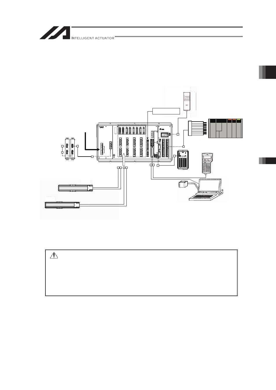
Chapter 2 Wiring
2.1 Wiring (Connection of devices) Diagram
2.1.1 XSEL-R
69
Chapter 2 Wiring
2.1 Wiring (Connection of devices) Diagram
2.1.1 XSEL-R
CONTROLLER
Panel Unit
(Option)
Host System
PLC
(Note 1)
Power Supply
3-phase or
Single-phase
AC200V
Regeneration Unit
(Option)
Extension I/O Unit
(Option)
PC
(Note 1)
PC Software
(Option)
Teaching Pendant
(Option)
Motor Cable
Encoder Cable
24V power supply
Power Supply for
Brake
(Note 1) (Note 2)
Flat Cable
�
�
Note 1
Please prepare separately.
Note 2 Supply of +24V power for brake to the controller is necessary if the actuator is
equipped with a brake.
�
�
Caution: In the case of ICSA, ICSPA (Orthogonal Robot) a number is attached to
each cable.
Connect it according to the controller connector number.
�
For the actuator regarded as that for single-axis robot, the connector Nos.
are not indicated.
�
In such case, give a number to each connector to avoid any mistake.
�
If the cable is not correctly connected, it might cause a damage to or
malfunction of the motor or PC board.
�
�