Bk pwr – IAI America XSEL-S User Manual
Page 127
Chapter 2 Wiring
2.3.1 Wiring for Power Supply Circuit
119
Parts Name
Model
Supplier
Position to Attach
1)
Noise Filter
MXB-1220-33
Densei Lambda
2)
Ring Core
ESD-R-25
NEC TOKIN
Attach in range of
300mm or less from
controller
�
3)
Clamp Filter
ZCAT3035-1330
TDK
4)
Clamp Filter
RFC-H13
Kitagawa Industries Co., Ltd.
Attach as close as
possible to controller
5)
Surge Protector
R·A·V-781BWZ-2A
Okaya Denki
Attach at the input
terminal of noise filter
(1) AC Power Supply Input Connector
Connector
Model
Remarks
Cable side
GMSTB2.5/6-STF-7.62
(PHOENIX CONTACT)
Enclosed in standard
package
Controller side
GMSTB2.5/6-7.62
(PHOENIX CONTACT)
Pin
No.
Signal name
Description
Applicable Wire Diameter
6
PE
Protective grounding wire
[Refer to Section 1.6.]
5
CP_L
Control power 200 VAC, phase L
4
CP_N
Control power 200 VAC, phase N
0.75mm
2
(AWG18)
3
NC
Disconnected
2
MP_L
Motor power 200 VAC, phase L
1
MP_N
Motor power 200 VAC, phase N
2mm
2
(AWG14)
PE
PWR
N
L
CP
MP
N
L
NC
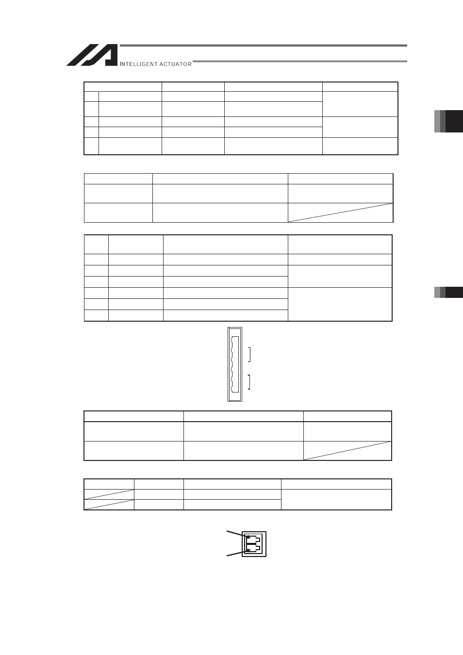
(2) Brake Power Connector
Connector
Model
Remarks
Cable side
MC1.5/2-ST-3.5
(PHOENIX CONTACT)
Enclosed in standard
package
Controller side
MC1.5/2-G-3.5
(PHOENIX CONTACT)
Pin No.
Signal name
Description
Applicable wire
+24V
24V Power Input
0V
24V Power Ground
0.14 to 1.5mm
2
(AWG28 to AWG16)
BK PWR
+24V
+
-
0V