IAI America XSEL-S User Manual
Page 129
Chapter 2 Wiring
2.3.2 Wiring the Emergency Stop Circuit (System I/O )
121
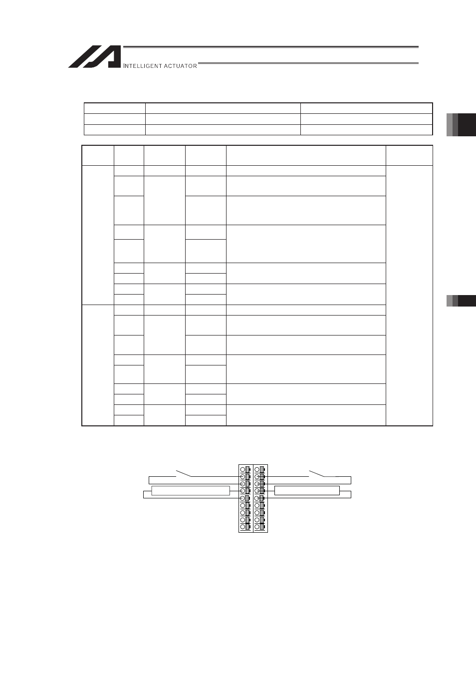
[1] R/RX/RXD type System I/O Connector
Connector
Model
Remarks
Cable side
FMC1.5/9-ST-3.5 (PHOENIX CONTACT) Enclosed in standard package
Controller side MCD1.5/9-G1-3.5P26THR�(PHOENIX CONTACT)
COMBICON (2 rows, 9 pins)
The product is delivered with jumper connection between the following pin numbers.
�
Pins 6 and 7
�
Pins 5 and 8
�
Pins 15 and 16
�
Pins 14 and 17�
Pin
No.
Signal
name
Category
Description
Applicable
wire
9
DET
IN
Not used
8
IN
Emergency stop detection input (relay
switch of the emergency stop circuit)
7
EMGin
*1
+24V
24-V power output for emergency stop
detection input (relay switch of the
emergency stop circuit)
6
line+
5
EMG1
*2
line-
Emergency stop switch 1 (emergency stop
circuit)
Wire circuit 1 connected to EMG of the
teaching pendant
4
line+
3
EMG2
line-
Not used
2
Out+
Left
Side
1
SDN
*3
Out-
External relay drive-source cutoff contact
output
18
DET
+24V
Not used
0.14 to
1.5mm
2
(AWG28 to
AWG16)
17
IN
Enable detection input (relay switch of the
safety gate circuit)
16
ENBin
*4
+24V
24-V power output for enable detection
input (relay switch of the safety gate circuit)
15
line+
14
ENB1
*5
line-
Enable switch 1 (safety gate circuit, etc.)
Wire circuit 1 connected to ENB of the
teaching pendant
13
line+
12
ENB2
line-
Not used
11
Out+
Right
Side
10
RDY
*6
Out-
Ready signal contact output (dry contact)
9
18
1 10
Cable side Connector
Left
Side
Right
Side
Safety Gate Circuit
Relay Switch of
the Safety Gate Circuit
Emergency Stop Circuit
Relay Switch of
the Emergency Stop Circuit