IAI America XSEL-S User Manual
Page 323
Chapter 6 Parameter
6.1 I/O Parameter (All types)
315
I/O Parameter (All types)
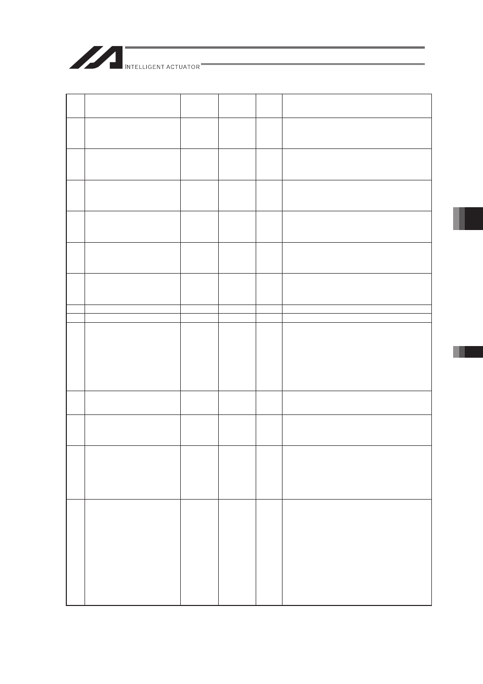
No.
Parameter name
Default
value
(reference)
Input
range
Unit
Remarks
521 Input port number for forced
release of RC axis 10 brake
0
0 to 3999
When the applicable port turns ON, the brake will
be released forcibly. (Beware of dropping axis.)
* Invalid, if 0. (Specification of input port No. 0 is
invalid.)
522 Input port number for forced
release of RC axis 11 brake
0
0 to 3999
When the applicable port turns ON, the brake will
be released forcibly. (Beware of dropping axis.)
* Invalid, if 0. (Specification of input port No. 0 is
invalid.)
523 Input port number for forced
release of RC axis 12 brake
0
0 to 3999
When the applicable port turns ON, the brake will
be released forcibly. (Beware of dropping axis.)
* Invalid, if 0. (Specification of input port No. 0 is
invalid.)
524 Input port number for forced
release of RC axis 13 brake
0
0 to 3999
When the applicable port turns ON, the brake will
be released forcibly. (Beware of dropping axis.)
* Invalid, if 0. (Specification of input port No. 0 is
invalid.)
525 Input port number for forced
release of RC axis 14 brake
0
0 to 3999
When the applicable port turns ON, the brake will
be released forcibly. (Beware of dropping axis.)
* Invalid, if 0. (Specification of input port No. 0 is
invalid.)
526 Input port number for forced
release of RC axis 15 brake
0
0 to 3999
When the applicable port turns ON, the brake will
be released forcibly. (Beware of dropping axis.)
* Invalid, if 0. (Specification of input port No. 0 is
invalid.)
527 (For expansion)
0
528 (For expansion)
0
529
Extension Motion Control
Board Synchronizing Main
CPU Control Main Axis Select
Axis Pattern
00111111B
0B to
11111111B
Select main CPU control axes available to indicate
at extension motion control board synchronizing
main axis (up to 6 axes at maximum)
Each bit = 1: extension motion control board
synchronizing main axis selectable
= 0: extension motion control board synchronizing
main axis not selectable
Note: Dedicated for XSEL-R/S controller
530
Number of Extension Motion
Control Board Position Data
Points
128
0 to 512
Maximum number of used position data points
Note: Dedicated for XSEL-R/S controller
531
Extension Motion Control
Board Position Data Definition
Maximum Axis Number
0
0 to 15
Maximum axis number to secure extension motion
control board axis position data domain in user
data retaining memory
Note: Dedicated for XSEL-R/S controller
532
Number of Position Data Points
for Extension Motion Control
Board Position Data Definition
0
0 to 512
Number of position data points to secure
extension motion control board axis position data
domain in user data retaining memory.
* Domain not secured when set to 0
* Domain secured when other than 0 no matter
if extension motion control board mounted
Note: Dedicated for XSEL-R/S controller
533
Extension Motion Control
Board Synchronizing Main
CPU Control Main Axis Position
Type
00000000H
0H to
FFFFFFFFH
Indicate main CPU control main axis (1
st
to 8
th
axes) synchronizing position type
(0: Current Order Position
1: Current Position)
Bits 0 to 3:
1
st
axis synchronizing position type
Bits 4 to 7:
2
nd
axis synchronizing position type
Bits 8 to 11: 3
rd
axis synchronizing position type
Bits 12 to 15: 4
th
axis synchronizing position type
Bits 16 to 19: 5
th
axis synchronizing position type
Bits 20 to 23: 6
th
axis synchronizing position type
Bits 24 to 27: 7
th
axis synchronizing position type
Bits 28 to 31: 8
th
axis synchronizing position type
Note: Dedicated for XSEL-R/S controller