IAI America XSEL-S User Manual
Page 216
Chapter 4
Absolute Reset and
Absolute Battery
4.1.1 For PC Software
208
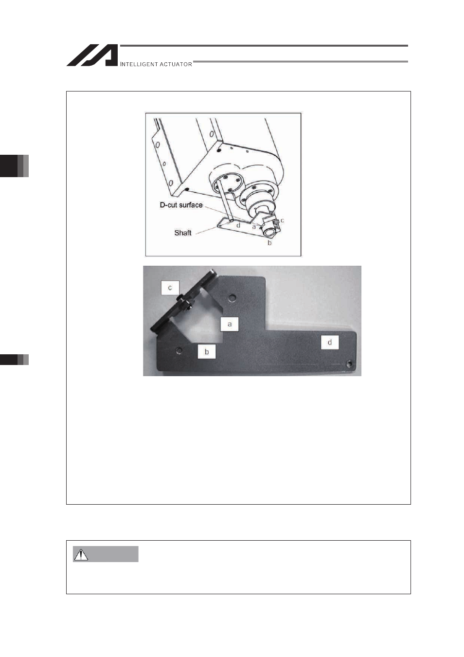
Jig Installation method
[1] Insert the ball-screw spline into the hole in the jig from below.
[2] Cause the D-cut surface of the ball-screw spline to contact the surface a.
[3] Cause the side surface of the ball-screw spline to contact the surface b.
[4] Tighten the screw c to secure the jig onto the ball-screw spline.
* At this time, confirm that the adjustment jig is vertical to the ball-screw spline and that the
D-cut surface and surface a are firmly in contact.
* Applicable screw: Hexagonal socket head setscrew M5
* Tightening torque: 20 [N•cm] (reference)
[5] Insert the supplied shaft into the hole in the ZR unit.
* Exercise caution because the shaft will come off if the hand is released.
[6] Turn the ball-screw spline until the supplied shaft contacts lightly with the surface d of the
jig.
�
Be sure to press the EMERGENCY STOP switch before setting an adjusting jig.
Failure to do so may cause a robot malfunction, which may lead to a serious accident resulting
in injury or death.
Warning