13 teaching tool – IAI America XSEL-S User Manual
Page 123
Chapter 2 Wiring
2.2.12 General-purpose RS232C Port Connectors
2.2.13
Teaching
Tool
115
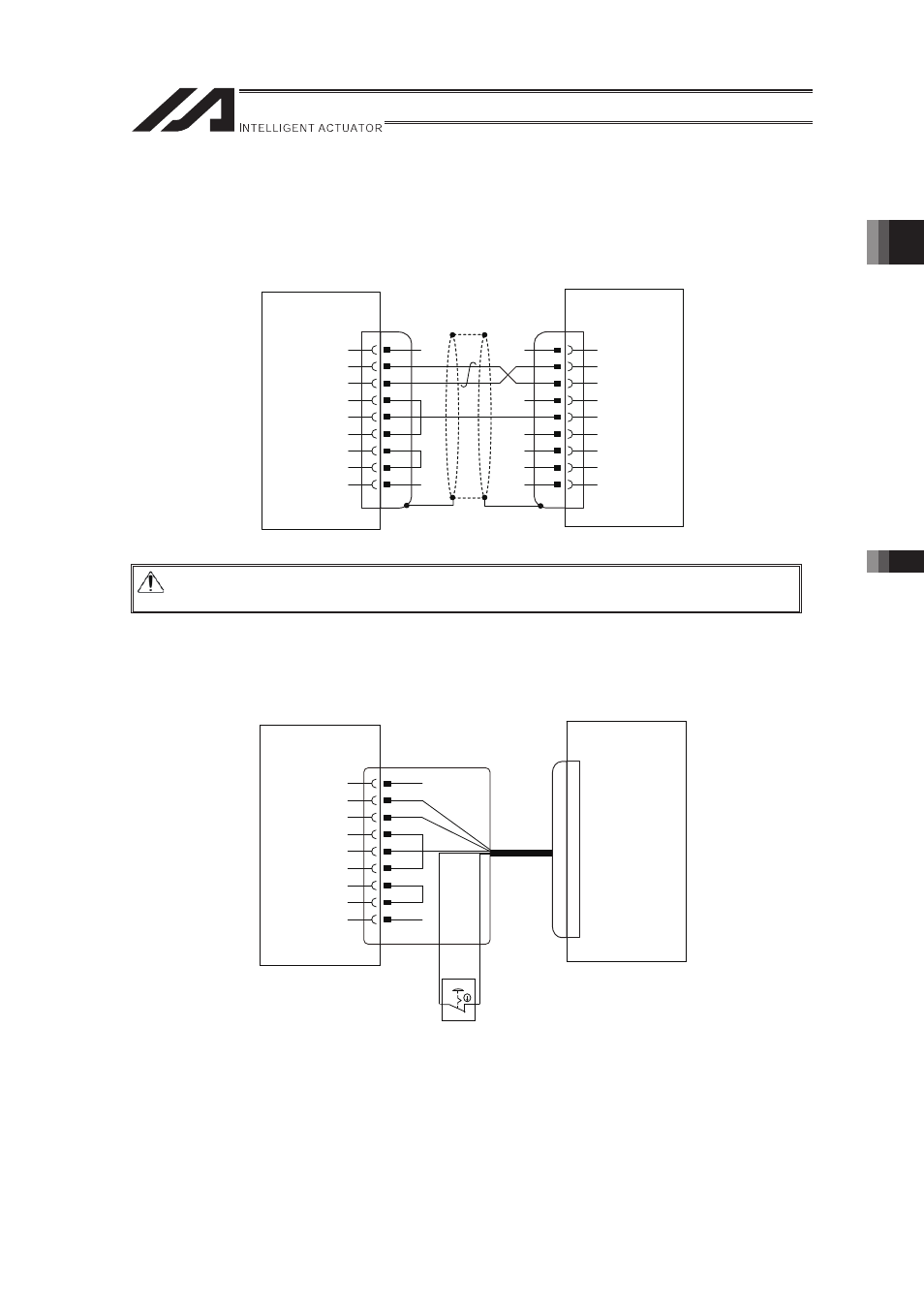
2.2.12 General-purpose RS232C Port Connectors
The following connecting diagram is for the case that the serial communication is performed from
the Host Controller.
Prepare a communication cable by the user.
CD
RD
SD
1
2
3
4
5
6
7
8
9
ER
SG
DR
RS
CS
NC
1
2
3
4
5
6
7
8
9
GV
CD
RD
SD
ER
SG
DR
RS
CS
Host Master (PLC, PC etc.)
General-purpose
RS232C Port Connectors
1 and 2
S1,S2
XSEL Controller
�
�
�
2.2.13 Teaching Tool
CD
RD
SD
1
2
3
4
5
6
7
8
9
ER
SG
DR
RS
CS
NC
Teaching
Connector
TP
Attached Emergency
Stop Switch Box
PC Software
Accessory Cable
Host Master
XSEL Controller
�
Caution: If the host master (PLC or PC) uses the flow control, connect ER (4 pins) and DR
(6 pins), RS (7 pins) and CS (8 pins) on the host master as shown in the figure.