IAI America XSEL-S User Manual
Page 36
28
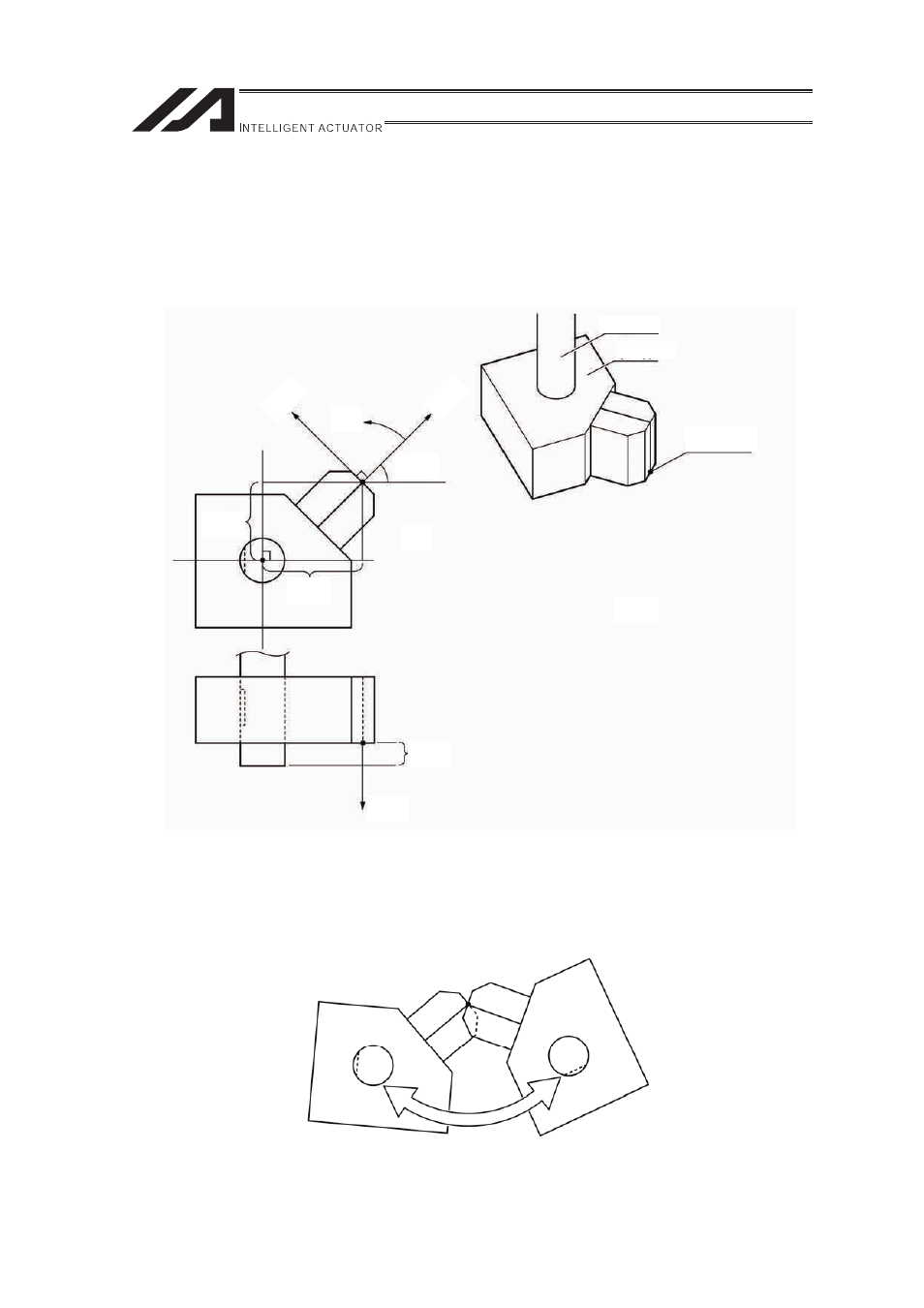
[Tool Coordinate System]
It is 128 types of the three-dimensional orthogonal coordinates + rotational axis coordinates
defined by the dimension (offset) of the tool (e.g. hand) attached on the tool attachment surface.
However, Work Coordinate System No. 0 is reserved as the tool coordinates offset 0 by the
system.
If the defined tool coordinate system number is selected, the tip of the tool, not the center of the
tool attachment surface, is used as the goal of the positioning.
Yoftn
Ytn
Xtn
Rtn
Roftn
Xoftn
Zoftn
Ztn
R axis
Tool
Tool Tip
Operation as shown below will be performed if the defined tool coordinate system is selected
and the jog operation is conducted on the R-axis.
Xoftn: X Tool Coordinate System Offset Level
Yoftn: Y Tool Coordinate System Offset Level
Zoftn: Z Tool Coordinate System Offset Level
Roftn: R Tool Coordinate System Offset Level
Xtn: Tool Coordinate System X Axis
Ytn: Tool Coordinate System Y Axis
Ztn: Tool Coordinate System Z Axis
Rtn: Tool Coordinate System R Axis
(n is Tool Coordinates Number)