IAI America NS User Manual
First edition, Model, 1] xy configuration directions
X-axis Nut-rotation Type Cartesian Robot
Assembly Procedures
First Edition
Thank you for purchasing an IAI product.
Assemble your product correctly by referring to this Assembly Procedures.
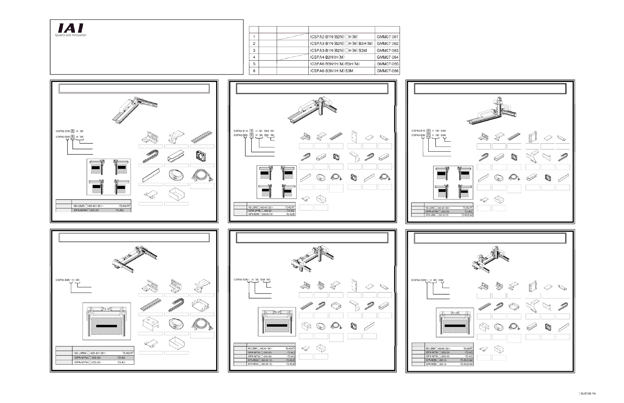
NS (nut-rotation type actuator) + ISA configuration unit
No.
Number of
configured axes
Z-axis installation method
Model Drawing
No.
2 axes
3 axes
3 axes
4 axes
6 axes
6 axes
Z-axis base mount
Z-axis slider mount
Z-axis base mount
Z-axis slider mount
X-axis Nut-rotation Type Cartesian Robot – High-precision 2-axis Specification
[Model]
H: X-axis high-speed type
M: X-axis medium-speed type
[1] XY configuration direction
1: Stroke 500 to 2200
2: Stroke 2250 to 3000
[1] XY configuration
directions
Configuration
direction: 1
(Range of
operation)
Configuration
direction: 2
(Reverse of 1)
(Range of
operation)
Configuration
direction: 3
(Y-axis installed
on opposite side)
(Range of
operation)
Configuration
direction: 4
(Reverse of 3)
(Range of
operation)
[Constituent axes]
Constituent axis
X-axis
Y-axis
Model
(stroke)
(stroke)
[1] XY bracket
[Assembled parts]
[2] Track mounting bracket
*
in the above models indicates either A (absolute) or I (incremental).
[3] Guide rail
[4] Cable track
[5] Connector box
[6] Box cover
[7] Joint cover
[8] Grommet with film
[9] Controller-actuator
cable with cable fix cap
[10] Cable guard
[11] Metal cover
[Assembly Procedure] Drawing No.: GMM07-061
X-axis Nut-rotation Type Cartesian Robot – High-precision 3-axis Specification,
Z-axis Base Mount
[Model]
H: Z-axis high-speed type
M: Z-axis medium-speed type
H: X-axis high-speed type
M: X-axis medium-speed type
[1] XY configuration direction
1: Stroke 500 to 2200
2: Stroke 2250 to 3000
[1] XY configuration directions
Configuration
direction: 1
(Range of
operation)
Configuration
direction: 2
(Reverse of 1)
(Range of
operation)
Configuration
direction: 3
(Y-axis installed
on opposite side)
(Range of
operation)
(Reverse of 3)
(Range of
operation)
[Constituent
axes]
Constituent axis
X-axis
Z-axis
Model
(stroke)
[1] XY
bracket
[Assembled parts]
*
in the above models indicates either A (absolute) or I (incremental).
[4] Cable
track 1
[7] Joint
cover 1
[9] Controller-
actuator cable
with cable
fix cap
[10] Cable
guard
[11] Metal
cover
[Assembly Procedure] Drawing No.: GMM07-062
Y-axis
(stroke)
(stroke)
[2] Track mounting
bracket 1
[3] Guide
rail
[5] Connector
box 1
[6] Box
cover 1
[8] Grommet
with film
[12] YZ
plate
[13] Track
mounting plate
[14] Track
support bracket
[15] Track
mounting bracket 2
[16] Cable
track 2
[17] Connector
box
[18] Box
cover 2
[19] Joint
cover 2
[20] Cable
fix cap
Configuration
direction: 4
X-axis Nut-rotation Type Cartesian Robot – High-precision 3-axis Specification,
Z-axis Slider Mount
[Model]
M: Z-axis medium-speed type
H: X-axis high-speed type
M: X-axis medium-speed type
[1] XY configuration direction
1: Stroke 500 to 2200
2: Stroke 2250 to 3000
[1] XY configuration directions
Configuration
direction: 1
(Range of
operation)
Configuration
direction: 2
(Reverse of 1)
(Range of
operation)
Configuration
direction: 3
(Y-axis installed
on opposite side)
(Range of
operation)
(Reverse of 3)
(Range of
operation)
[Constituent
axes]
Constituent axis
X-axis
Z-axis
Model
(stroke)
[1] XY
bracket
[Assembled parts]
*
in the above models indicates either A (absolute) or I (incremental).
[4] Cable
track 1
[7] Joint
cover 1
[9] Controller-
actuator cable
with cable
fix cap
[10] Cable
guard
[11] Metal
cover
[Assembly Procedure] Drawing No.: GMM07-063
Y-axis
(stroke)
(stroke)
[2] Track mounting
bracket 1
[3] Guide
rail
[5] Connector
box 1
[6] Box
cover 1
[8] Grommet
with film
[12] YZ
bracket
[13] Track
mounting plate
[14] Track
support bracket
[15] Track
mounting bracket 2
[17] Cable
track 2
[19] Box
cover 2
[20] Joint
cover 2
Configuration
direction: 4
[16] Track
mounting bracket 3
[18] Connector
box 2
X-axis Nut-rotation Type Cartesian Robot – High-precision 4-axis Specification
[Model]
H: X-axis high-speed type
M: X-axis medium-speed type
[1] XY configuration direction
[1] XY configuration directions
Configuration direction: 1
(Range of operation)
[Constituent axes]
Constituent axis
X-axis
Model
(stroke)
(stroke)
[1] XY bracket
[Assembled parts]
[2] XY bracket
*
in the above models indicates either A (absolute) or I (incremental).
[3] Track mounting bracket
[4] Guide rail
[5] Cable track
[6] Wiring box bracket
[7] Wiring box cover
[8] Grommet with film
[9] Controller-actuator
cable with cable fix cap
[10] Cable guard
[11] Metal cover
[Assembly Procedure] Drawing No.: GMM07-064
X-axis Nut-rotation Type Cartesian Robot – High-precision 6-axis Specification,
Z-axis Base Mount
[Model]
H: Z-axis high-speed type
M: Z-axis medium-speed type
H: X-axis high-speed type
M: X-axis medium-speed type
[1] XY configuration direction
[1] XY configuration directions
[Constituent axes]
Constituent axis
X-axis
Model
(stroke)
[1] XY
bracket
[Assembled parts]
*
in the above models indicates either A (absolute) or I (incremental).
[4] Guide
rail
[7] Wiring
box cover
[9] Controller-
actuator cable
with cable
fix cap
[10] Cable
guard
[11] Metal
cover
[Assembly Procedure] Drawing No.: GMM07-065
(stroke)
(stroke)
[2] XY
bracket
[3] Track mounting
bracket
[5] Cable
track
[6] Wiring
box bracket
[8] Grommet
with film
[12] YZ
plate
[13] Track
mounting plate
[14] Track
support bracket
[15] Track
mounting bracket 2
[16] Cable
track 2
[17] Connector
box 2
[18] Box
cover 2
[19] Joint
cover 2
X-axis Nut-rotation Type Cartesian Robot – High-precision 6-axis Specification,
Z-axis Slider Mount
[Model]
M: Z-axis medium-speed type
H: X-axis high-speed type
M: X-axis medium-speed type
[1] XY configuration direction
[1] XY configuration directions
[Constituent axes]
Constituent axis
X-axis
Model
(stroke)
[1] XY
bracket
[Assembled parts]
*
in the above models indicates either A (absolute) or I (incremental).
[4] Guide
rail
[7] Wiring
box cover
[9] Controller-
actuator cable
with cable
fix cap
[10] Cable
guard
[11] Metal
cover
[Assembly Procedure] Drawing No.: GMM07-066
(stroke)
(stroke)
[2] XY
bracket
[3] Track
mounting bracket
[5] Cable
track
[6] Wiring
box bracket
[8] Grommet
with film
[12] YZ
bracket
[13] Track
mounting plate
[14] Track
support bracket
[15] Track
mounting bracket 2
[17] Cable
track 2
[19] Box
cover 2
[20] Joint
cover 2
[16] Track
mounting bracket 3
[18] Connector
box 2
Y1-axis
Y2-axis
(stroke)
Y1-axis
Y2-axis
Z1-axis
Z2-axis
(stroke)
(stroke)
(Range of operation)
Configuration direction: 1
(Range of operation)
Configuration direction: 1
Y1-axis
Y2-axis
Z1-axis
Z2-axis
(stroke)
(stroke)
Catalog No.