IAI America XSEL-S User Manual
Page 48
Chapter 1 Specifications Check
1.2.1 XSEL-R/S Controller
Type
40
[Calculation Example]
Shown below is an example for how to calculate the power capacity and amount of heat
generation when the following actuators are used.
Axis 1 Actuator 200W�
Axis 2 Actuator 200W�
Axis 3 Actuator 100W�w/ brake� Axis 4 Actuator 60W�
Standard type Controller�Option: PIO Board 1 sheet,, Device Net
Teaching Pendant (IAI Standard Type)�
�
�
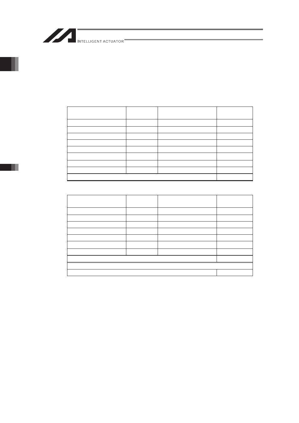
1) Control Power Capacity�
Base Unit
Quantity
Power consumption
(Per Unit)
Total [VA]
Base Unit
�
31.4
31.4
Driver
2
6.26
12.52
Encoder
4
2.38 + 3.57
23.8
Fan Unit
6
5.71
34.26
PIO Board
1
5.95
5.95
Device Net
�
1.98
1.98
Teaching pendant
1
3.57
3.57
Brake
1
0.14
0.14
Totalizer
113.62
2) Heat Generation of Control System
Base Unit
Quantity
Power consumption
(Per Unit)
Total [VA]
Base Unit
�
31.4
31.4
Driver
2
6.26
12.52
Encoder
4
2.38
9.52
Fan Unit
6
5.71
34.26
PIO Board
1
5.95 + 14.52
20.47
Device Net
�
1.98 + 3.43
5.41
Brake
1
2.64
2.64
Totalizer
116.22
Heat Generation [W] = Totalizer [VA] × 0.7(Efficiency)×0.6(Power Factor)
48.81
�
3) I/O (PIO Board Board ) Power Capacity (24V DC)�
14.52 × 1 = 14.52 [VA]
�
4) Brake Power Capacity (24V DC)
(2.5 + 5.8) ×1 = 8.3 [VA]
5) Motor Power Capacity
421 + 421 + 234 + 138 = 1214 [VA]
6) Motor Power Supply Heat Generation
9.12 + 9.12 + 6.12 + 3.39 = 27.75 [W]
�
7) Rated Power Capacity =
1) Control Power Capacity + 5) Motor Power Capacity = 113.62 + 1214 = 1327.62 [VA]
8) Heat Generation =
2) Heat Generation of Control System + 6) Motor Power Supply Heat Generation = 48.81
+ 27.75 = 76.56 [W]