IAI America XSEL-S User Manual
Page 143
Chapter 2 Wiring
2.3.8 W
ring for Brake Box (RCB-1
10-RA13-0)
135
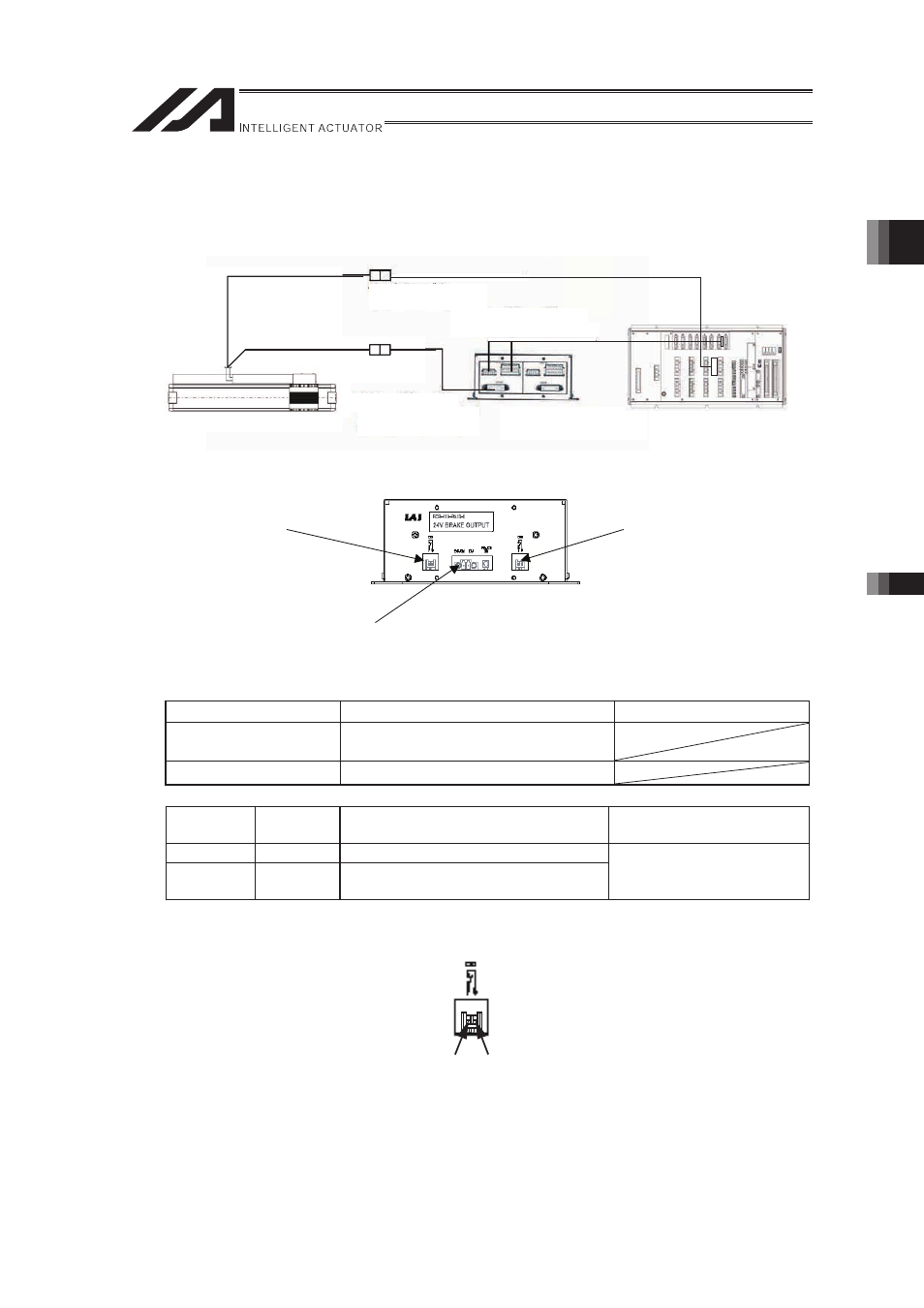
2.3.8 Wiring for Brake Box (RCB-110-RA13-0)
As shown in the figure below, connect the actuator, brake box and controller. (the figure is an
example for connecting to the 1
st
axis.)
Controller
Rear View
External Brake Connector Box
(RCB-110-RA13-0)
Encoder Cable
(CB-X3-PA□□□)
Actuator
Encoder Cable
(CB-X1-PLA□□□)
Motor Cable
(CB-X-MA□□□)
(1) Brake Release Switch Connector 1 and 2
Connector
Model
Remarks�
Cable side
XAP-02V-1
Contact BXA-001T-P0.6 (JST)
�
Applied Connector
S02B-XASS-1 (JST)
�
�
Pin No.
Signal
Name
Description
Applicable Wire Diameter
1
BKMRL
Brake Release Switch Input�
2
COM
Brake Release Switch Input
Common�
0.08 to 0.3mm
2
(AWG28 to 22)
�
2), 3) Brake Release Connector 1 and 2
For the switch, select one rated 30V DC and 1.5mA or more.
Front
3) Brake Release
Switch Connector 2
2) Brake Release
Switch Connector 1
1) Brake Power Input
Connector
1
2