IAI America XSEL-S User Manual
Page 373
Chapter 6 Parameter
6.3.2 For XSEL-RX/SX, RXD/SXD
365
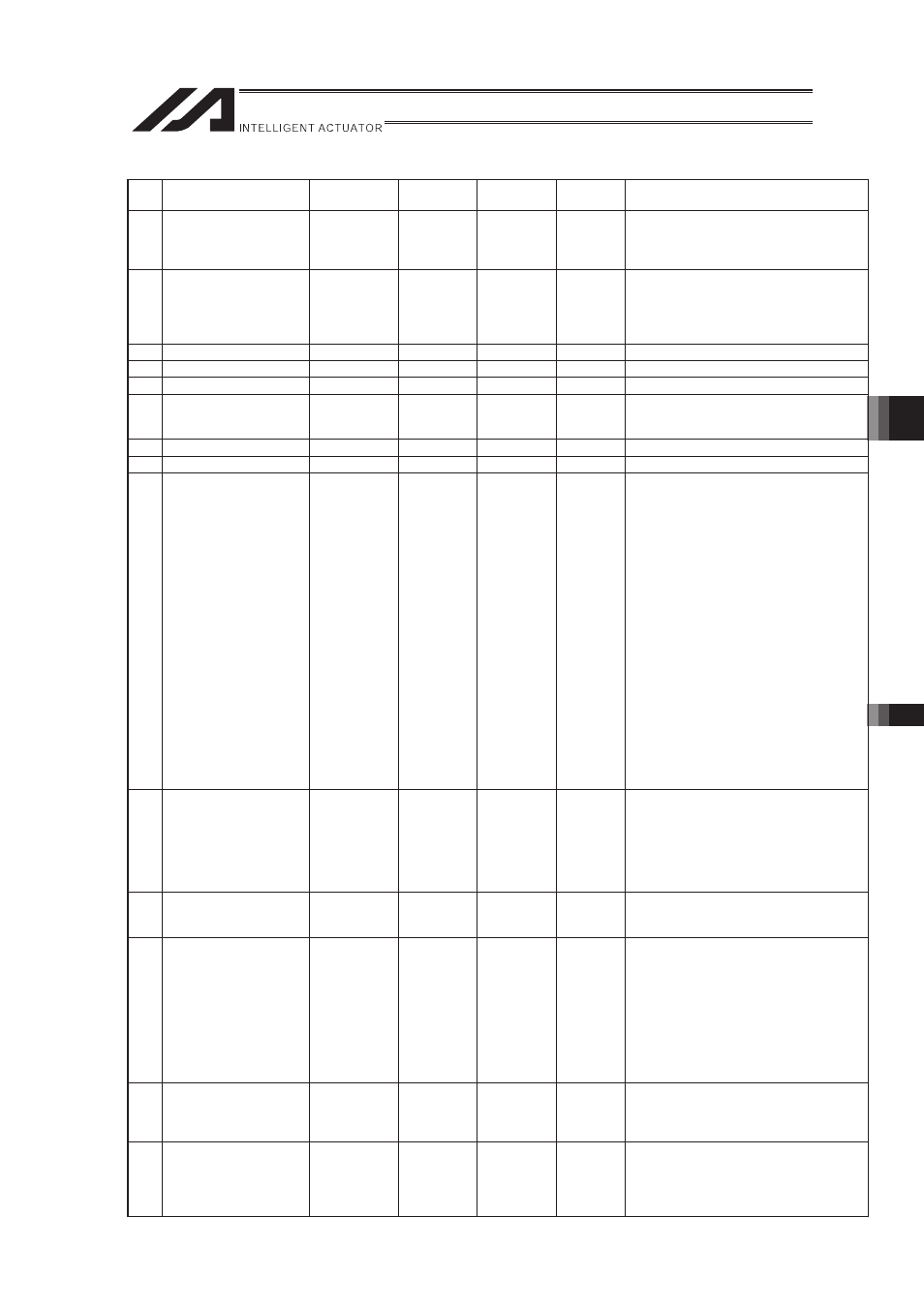
Axis-Specific Parameters (XSEL-RX/SX, RXD/SXD)
No.
Parameter name
Default value
(reference)
Input range
Unit
Remarks
No.
96 Linear Sliding Axis Zone
4 MIN
0
0
-99999999
to 99999999 0.001mm
Valid only when Max. > Min.
* Necessary to secure 3msec or more for
domain going-through time
Note: Valid only on linear sliding axes
97 Linear Sliding Axis Zone
4 Output No.
0
0
0 to 6999
Physical output port or Global Flag or
Extended Output Ports
(Output invalid when set to 0, invalid when
duplicated))
Note: Valid only on linear sliding axes
98 (For expansion)
0
0
99 (For expansion)
0
0
100 (For expansion)
0
0
101
Allowable Time for
Excess of Continuous
Operational Torque
0
0
0 to 300
s
Not to monitor excess time of continuous
operational torque when set to 0
102 (For expansion)
0
0
103 (For expansion)
0
0
104
Axis Select for Appliance
of Multi-Slider
Overapproach Detection
0H
0H
0H to
FFFFFFFFH
Bits 0 to 3: Mating axis number to apply
overapproach detection
(self-axis coordinate positive
movement side)
Bits 4 to 7: Mating axis number to apply
overapproach detection
(self-axis coordinate negative
movement side)
* Necessity of mutual input with
mating axis (The smaller axis
number in a pair is the multi-slider
master axis for convenience.)
* Axes with same characteristics on
resolution related are available to
select.
* Make sure to select the
synchro-master axis when
synchronizing type (forbidden to
select synchro-slave axes).
* Set to 0 when there is no slider close
to the side of applicable movement
of the self-axis coordinate.
105 Multi-Slider Effective
Stroke
0
0
0 to
99999999
0.001mm
Set [Allowable furthest distance between
sliders] – [Allowable closest distance
between sliders] in the operational range
of the two axes applicable for the
multi-slider overapproach detection.
(Valid only on multi-slider master axis
parameters)
106
Emergency Deceleration
Margin at Multi-Slider
Overapproach
5
5
0 to 999
0.01G
107 Multi-Slider Setting Bit
Pattern 1
12H
12H
0H to
FFFFFFFFH
Bits 0 to 3: Multi-slider actual position
overapproach detection margin
(mm)
(Valid only on multi-slider
master axis parameters)
Bits 4 to 7: Multi-slider commanded
position overapproach
detection margin (mm)
(Valid only on multi-slider
master axis parameters)
108
Control Switchover
Width in Linear Sliding
Axis Synchro-Slave Axis
Positioning
5000
5000
1 to 99999
0.001mm
Valid only for synchro-slave axes
* Related Information: Each Axis
Parameter No.52
109
Ball Screw Spline
(Linear Sliding Axis +
Rotation Movement
Axis) Adjustment Mating
Axis Select
0
0
0 to 8
Mutual input required
0: Disable
1 to 8: Mating axis number
* Related Information: Each Axis
Parameter No.1