6 noise prevention and the installation – IAI America XSEL-S User Manual
Page 73
Chapter 1 Specifications Check
1.6 Noise Prevention and the Installation
65
1.6 Noise Prevention and the Installation
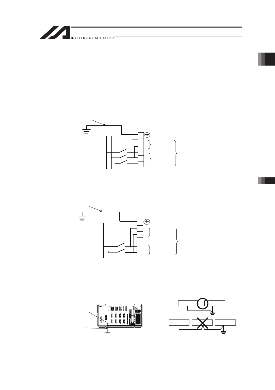
(1) Protective Ground
For the grounding, the grounding resistance should be set to 100� or less.
The wiring should apply a twist line or an annealed copper wire of 2.0 mm
2
(AWG14) or more.
Apply 3.5mm2 or more for XSEL-SX-NNN10040 and 12040.
[3-Phase Type]
L
N
R
S
T
1
L 2
L 3
L
For Motor
Driving
AC Power Supply
Input Connector
Grounding resistance
at 100Ω or less
For Control
AC Power Supply Input
Strand or annealed copper wire:
Connect with an earth line of
2.0mm
2
(AWGN) or more
Apply 3.5mm2 or more for
XSEL-SX-NNN10040 and 12040.
�
�
�
[Single-Phase Type]
�
L
N
L
N
L N
For Motor
Driving
AC Power Supply
Input Connector
Grounding resistance
at 100Ω or less
For Control
AC Power Supply Input
Strand or annealed copper wire:
Connect with an earth line of
2.0mm
2
(AWGN) or more
�
�
�
(2) Noise Elimination Grounding (Frame Ground)
For grounding, make sure to conduct Class D Grounding (grounding resistance 100� or less).
Apply annealed twist wire or copper wire cables with 2.0 mm
2
(AWG14) or more for wiring and
connect with solderless ring tongue terminals.
�
�
Controller
Controller
Other Equipment
Other Equipment
Other Equipment
Do not share the ground wire with or connect to other equipment.
Ground each controller separately.
Grounding resistance at 100Ω or less
Attach the grounding
cable to the FG terminal
on the main machine.
Strand or annealed copper wire:
Connect with an earth line of
2.0mm
2
(AWGN) or more
Apply 3.5mm2 or more for
XSEL-SX-NNN10040 and
12040.