IAI America XSEL-S User Manual
Page 105
Chapter 2 Wiring
2.2.7 PIO Circuit
97
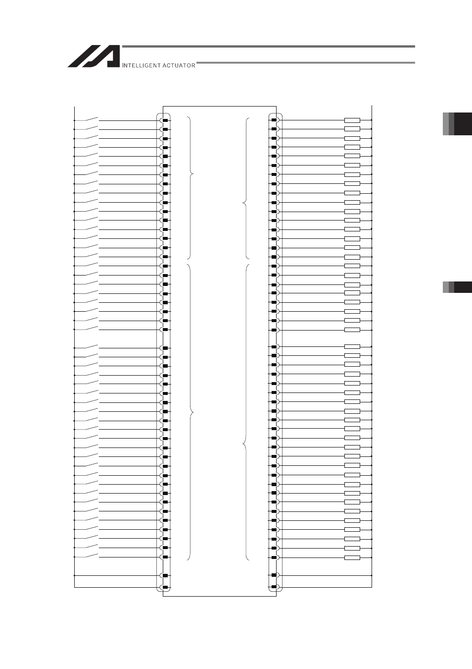
� 48 Input Points / 48 Output Points (Display of XSEL Mode Code: P3)
000
001
002
003
004
005
006
007
008
009
010
011
012
013
014
015
016
017
018
019
020
021
022
023
024
025
026
027
028
029
030
031
032
033
034
035
036
037
038
039
040
041
042
043
044
045
046
047
300
301
302
303
304
305
306
307
308
309
310
311
312
313
314
315
316
317
318
319
320
321
322
323
324
325
326
327
328
329
330
331
332
333
334
335
336
337
338
339
340
341
342
343
344
345
346
347
Load
(Red-1)
(Orange-1)
(Yellow-1)
(Green-1)
(Blue-1)
(Purple-1)
(Gray-1)
(White-1)
(Black-1)
(Brown-2)
(Red-2)
(Orange-2)
(Yellow-2)
(Green-2)
(Blue-2)
(Purple-2)
(Gray-2)
(White-2)
(Black-2)
(Brown-3)
(Red-3)
(Orange-3)
(Yellow-3)
(Green-3)
(Purple-3)
(Gray-3)
(White-3)
(Black-3)
(Brown-4)
(Red-4)
(Orange-4)
(Yellow-4)
(Green-4)
(Blue-4)
(Purple-4)
(Gray-4)
(White-4)
(Black-4)
(Brown-5)
(Red-5)
(Orange-5)
(Yellow-5)
(Green-5)
(Blue-5)
(Purple-5)
(Gray-5)
(White-5)
(Black-5)
(Green-3)
(Black-5)
(Brown-1)
(Red-1)
(Orange-1)
(Yellow-1)
(Green-1)
(Blue-1)
(Purple-1)
(Gray-1)
(White-1)
(Black-1)
(Brown-2)
(Red-2)
(Orange-2)
(Yellow-2)
(Green-2)
(Blue-2)
(Purple-2)
(Gray-2)
(White-2)
(Black-2)
(Brown-3)
(Red-3)
(Orange- )
(Yellow-3)
(Blue-3)
(Purple-3)
(Gray-3)
(White-3)
(Black-3)
(Brown-4)
(Red-4)
(Orange-4)
(Yellow-4)
(Green-4)
(Blue-4)
(Purple-4)
(Gray-4)
(White-4)
(Black-4)
(Brown-5)
(Red-5)
(Orange-5)
(Yellow-5)
(Green-5)
(Blue-5)
(Purple-5)
(Gray-5)
(White-5)
(Brown-1)
(Blue-3)
0V common
0V common
24V common
24V common
2
3
4
5
6
7
8
9
10
11
12
13
14
15
16
17
18
19
20
21
22
23
24
25
27
28
29
30
31
32
33
34
35
36
37
38
39
40
41
42
43
44
45
46
47
48
49
50
75
100
51
52
53
54
55
56
57
58
59
60
61
62
63
64
65
66
67
68
69
70
71
72
73
74
76
77
78
79
80
81
82
83
84
85
86
87
88
89
90
91
92
93
94
95
96
97
98
99
1
26
0 V
24 V
I/O Board
Stated in () is a Wirer color of the supplied flat cable
Universal output
Universal Input
Input function
is parameter
setup
Output function
is parameter
setup
The second (Slot No. 2) PIO board No., is decided with the I/O parameter No. 1 to 5 setting.
�