IAI America XSEL-S User Manual
Page 112
Chapter 2 Wiring
2.2.10 Extension I/O unit (Option)
104
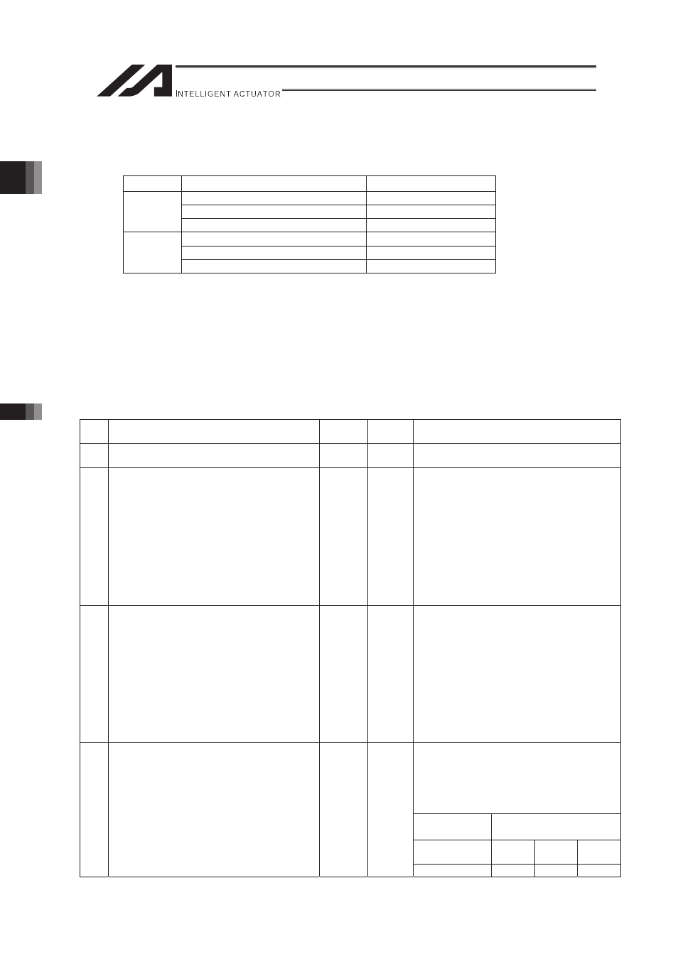
(2) Connection of PIO
There are six types of PIO board which are the identical to the ones to be
attached in the XSEL main machine.
Polarity
No. of I/O points
Model
32 Input Points / 16 Output Points
IA-103-X-32
16 Input Points / 32 Output Points
IA-103-X-16
NPN
48 Input Points / 48 Output Points
IA-IO-3204-NP
32 Input Points / 16 Output Points
IA-103-X-32-P
16 Input Points / 32 Output Points
IA-103-X-16-P
PNP
48 Input Points / 48 Output Points
IA-IO-3204-PN
For the extension I/O units, four boards out of the above boards can be attached.
The port allocation setting using the I/O parameters is required to use this PIO board.
�
I/O Port Allocation
For the I/O parameter No. 1, the allocation is fixed.
The port Nos. which can be allocated to the extension I/O unit, are 1000 to 3999 for input and
4000 to 6999 for output.
Set the I/O parameter No. 707 through 714 for the port Nos., to be used on the I/O board
attached to each slot.
No.
Parameter name
Set in
Delivery
Set
Value
Details of Parameters
1
I/O Port Allocation Type
1
0
0: Fixed Allocation
1: Automatic Allocation
707 Extension Input Port Start Number at
Extension I/O Unit Slot 1 Fixed Assignment
-1
1000
1000+n� (Multiples of 16)
When it is not to be used, set it to “-1”.
Set the head address for the extension
output.
�
EtheCAT is not used
Normally, it is set to “1000”.
�
EtherCAT is used
�
For the EtherCAT, the address has
been allocated from the head
address 1000 at the delivery.
Have
the setting not duplicated.
708 Extension output Port Start Number at
Extension I/O Unit Slot 1 Fixed Assignment
-1
4000
4000+n� (Multiples of 16)
When it is not to be used, set it to “-1”.
Set the head address for the extension
output.
�
EtheCAT is not used
Normally, it is set to “4000”.
�
EtherCAT is used
�
For the EtherCAT, the address has
been allocated from the head
address 4000 at the delivery.
Have
the setting not duplicated.
1000+n (Multiples of 16)
When it is not to be used, set it to “-1”.
Set the address following to the slot No.1’s
input address.
Set Value = (Slot No. 1’s Input Address) +
(No. of Inputs of the Slot No. 1)(Example)
Slot 1
Top Address
Slot 11
Number of Input Points
1000
32
points
16
points
48
points
709 Extension Input Port Start Number at
Extension I/O Unit Slot 2 Fixed Assignment
-1
Refer
to the
Right
Box.
Set Value
1032
1016
1048