IAI America XSEL-S User Manual
Page 357
Chapter 6 Parameter
6.3.1 For XSEL-R/S
349
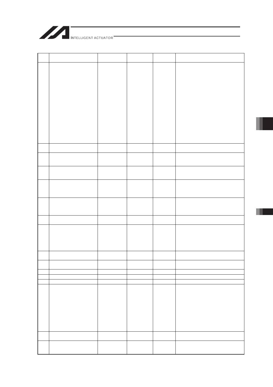
Axis-Specific Parameters (XSEL-R/S)
No.
Parameter name
Default value
(reference)
Input range
Unit
Remarks
52 Synchronizing Setting Bit
Pattern 1
0
0H to
FFFFFFFFH
(2) Turn the servo off by emergency
stop.
(3) Align the physical position
relation of the synchro-master
axis and slave axis to read the
current position coordinates.
(4) Calculate “Synchro-slave axis
current position coordinates –
Synchro-master axis current
position coordinates” and set the
figured out value to “Each Axis
Parameter No. 21 Offset
Movement Amount in
Home-Return” on the
synchro-slave axis side. (Be
careful of unit conversion)
(5) Controller soft reset or power-on
reset after flash ROM writing
*Valid only for synchro-slave axes
53 Each Axis Setting Bit
Pattern 1
0
0H to
FFFFFFFFH
54
Pressing Stop Detection
Movement Amount in
Home-Return
20
1 to 99999
0.001mm
Used in pressing check in home-return
operation
55
Pressing Stop Detection
Movement Amount in
Pressing
30
1 to 99999
0.001mm
Used in pressing check in PUSH
Command
56
Pressing Compulsory
Complete Deviation in
Home-Return
2000
1 to 99999
Compare [Pressing velocity steady-state
error + Pressing speed pulse velocity �
compulsory complete deviation] and
deviation
57
Pressing Compulsory
Complete Deviation at
Positioning
5000
1 to 99999
Compare [Pressing velocity steady-state
error + Pressing speed pulse velocity �
compulsory complete deviation] and
deviation
58 Positioning width
100
1 to 9999
0.001mm
0.001deg
* Related Information: Each Axis
Parameter No.52
59
Deviation Error Allowable
(Maximum Velocity Pulse
Ratio)
27
1 to 99
Maximum steady-state error in
operational velocity for each axis +
maximum pulse speed in operational
velocity for each axis � comparison of
deviation error allowable rate and
deviation
60 Position Gain
30
1 to 9999
/s
* Change prohibited unless any
indication from the supplier
61 FAG
0
0 to 999
* Change prohibited unless any
indication from the supplier
62 Synchronizing FB Gain
77
0 to 1000
/s
63 Special Stop Output Range
1
0 to 9999
Pulse
Invalid when set to 0.
64 Special Stop Output Value
1
0 to 999
DRVVR
65 Synchronized Mating Axis
Number
0
0 to 8
Necessity of mutual input (The smaller
axis number in a pair is the master axis.
Axes with same characteristics on
resolution related are available to select.
Command issuance to slave axis is
unavailable.)
* It is necessary to install the actuator
with the “home-return end positions”
on the synchro-master and slave axes
being physically aligned.
(Invalid when set to 0.)
66 Rotation Movement Axis
Mode Select
0
0 to 5
0: Normal, 1: Index Mode
67
Short-cut control selection
for rotational movement
axis
0
0 to 5
0: Not selected, 1:Selection (Effective
only when Index Mode and INC
encoder)