IAI America XSEL-S User Manual
Page 147
Chapter 2 Wiring
2.3.10 Wiring the Brake Forced Release Switch
139
2.3.10 Wiring the Brake Forced Release Switch
This connector is used to connect the brake release switch on the actuator (it functions in the
same way as the brake switch on the controller).
Short-circuiting the COM and BKRMT terminals of this connector releases the brake. Use this
method if you want to manually move the actuator while the controller power is cut off or a
controller error is present.
For the switch, select one for minute load.
� Brake Release Switch Connector Specifications�
Connector
Model
Remarks
Cable side
DF11-6DS-2C
Crimp terminal: DF11-2428SC
(Hirose)
Controller side
DF11-6DP-2DS (Hirose)
Pin No.
Signal Name
Description
Applicable
Wire Diameter
1
BKRMT1(BKRMT5) Brake Release Switch Input Axis 1(5)
2
BKRMT2(BKRMT6) Brake Release Switch Input Axis 2(6)
3
BKRMT3(BKRMT7) Brake Release Switch Input Axis 3(7)
4
BKRMT4(BKRMT8) Brake Release Switch Input Axis 4(6)
5
COM(COM)
Switch Input Common
6
COM(COM)
Switch Input Common
0.08 to
0.2mm
2
(AWG28 to 22)
Those in the brackets are the signal names and signal contents of BK RMT2 connector�
For the switch, select one rated 24V DC and 100mA or more.
� �
Warning: After brake compulsory release is conducted, make sure to turn the signal
OFF so the automatic control of brake by controller can be executed. It is
extremely risky to leave it turned ON because the brake would not work
when in emergency stop or the servo is turned OFF. For a vertically
mounted actuator, slider or rod may drop and cause a critical accident.
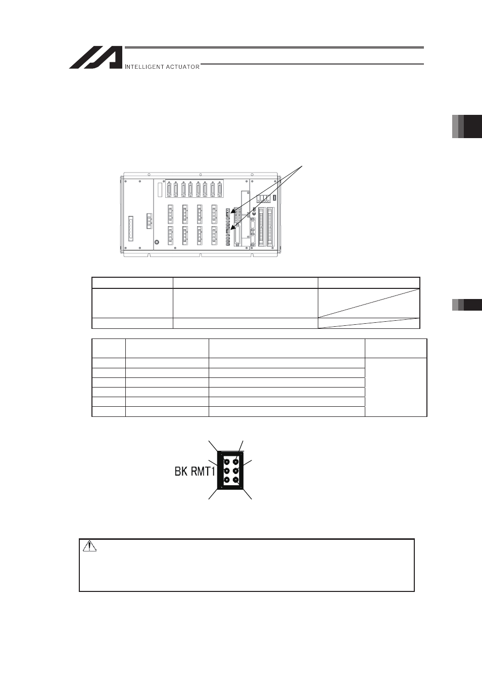
6
5
4
3
1
2
Brake Release Switch Connector