1 i/o parameter (all types) – IAI America XSEL-S User Manual
Page 287
Chapter 6 Parameter
6.1 I/O Parameter (All types)
279
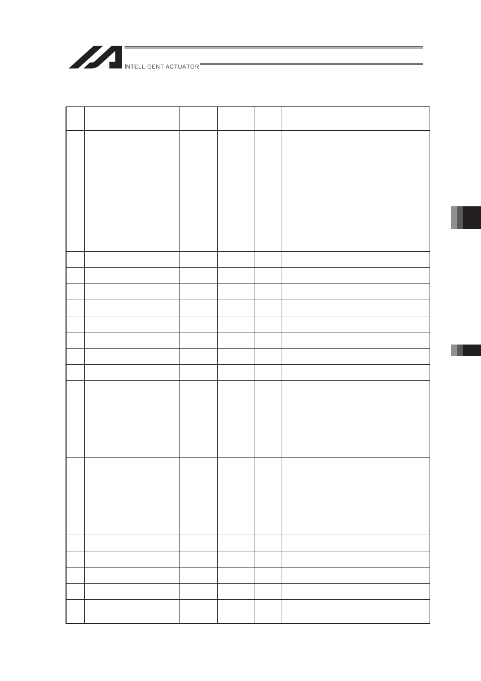
6.1 I/O Parameter (All types)
No.
Parameter name
Default
value
(reference)
Input
range
Unit
Remarks
1 I/O port assignment type
1
0 to 20
0: Fixed assignment
1: Automaticassignment
* Priority of I/O port assignment at automatic
assignment
(No.0 to 299/No.300 to 599)
(Network I/F Module 1 � I/O slot 1 (I/O1)
Mounting board to)
* Assigned for the range of continuous
mounting from I/O slot 1 (I/O1) Mounting
board = for safety
* Priority of extension I/O ports at automatic
assignment
(No.1000 to 3999/No.4000 to 6999)
(Network I/F Module 2 � Extension I/O unit
� Communication between IA Net
Controllers)
2 I/O Slot 1 Fix-Allocated Input
Port Start No. (I/O 1)
000
-1 to 299
0+(multiple of 8)(Invalid if a negative value is set.)
3 I/O Slot 1 Fix-Allocated Output
Port Start No. (I/O 1)
300
-1 to 599
300+(multiple of 8)(Invalid if a negative value is
set.)
4 I/O Slot 2 Fix-Allocated Input
Port Start No. (I/O 1)
-1
-1 to 599
0+(multiple of 8)(Invalid if a negative value is set.)
5 I/O Slot 2 Fix-Allocated Output
Port Start No. (I/O 1)
-1
-1 to 599
300+(multiple of 8)(Invalid if a negative value is
set.)
6 Reserved by the system
(change is prohibited)
0
7 Reserved by the system
(change is prohibited)
0
8 Reserved by the system
(change is prohibited)
0
9 Reserved by the system
(change is prohibited)
0
10 I/O Slot 1 Error Monitor (I/O1)
1
0 to 5
0: Do not monitor
1: Monitor
2: Monitor (Do not monitor 24-V I/O power errors)
3: Monitor (Monitor 24-V I/O power errors)
* Some exceptions apply.
* If 0 (= Do not monitor) or 2 (= Monitor (Do not
monitor 24-V I/O power errors)) is set, outputs
from digital I/O boards are disabled to protect the
controller when a 24-V I/O power error occurs,
although a system error does not generate.
11 I/O Slot 2 Error Monitor (I/O2)
1
0 to 5
0: Do not monitor
1: Monitor
2: Monitor (Do not monitor 24-V I/O power errors)
3: Monitor (Monitor 24-V I/O power errors)
* Some exceptions apply.
* If 0 (= Do not monitor) or 2 (= Monitor (Do not
monitor 24-V I/O power errors)) is set, outputs
from digital I/O boards are disabled to protect the
controller when a 24-V I/O power error occurs,
although a system error does not generate.
12 Reserved by the system
(change is prohibited)
0
13 Reserved by the system
(change is prohibited)
0
14 No. of Network I/F Module
Remote Input Ports
0
0 to 256
Multiples of 8
15 No. of Network I/F Module
Remote Output Ports
0
0 to 256
Multiples of 8
16
Network I/F Module 1
Fix-Allocated Input Port Start
No.
-1
-1 to 3999
0+(Multiples of 8)(0 to 299)
1000+(Multiples of 8)(1000 to 3999)(Invalid if a
negative value is set.)