Starting procedures – IAI America XSEL-S User Manual
Page 37
29
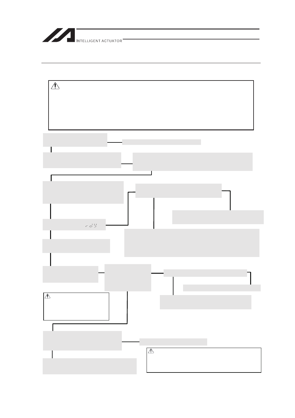
Starting Procedures
When using this product for the first time, work while making sure to avoid omission and incorrect
wiring by referring to the procedure below.
� �
Warning: • Make sure to put the brake release switch on the controller on the right
(NOM) when booting the power.�
If it is on the left (RLS) side, it may cause a drop of actuator by its own
weight and may pinch a part of your body or damage the work piece.�
• Always connect the controller to the robot whose serial number is
indicated on the controller.�
Connecting a robot out of indication may cause a controller burned down
or wrong operation.�
�Yes
Connect the motor cable. [Refer to 2.3.3.]
No�
�
To ensure safety, it is recommended that safety speed be
enabled during initial movements.
� When the actuator is installed vertically , be careful so you would
not pinch your hand or damage the robot hand with the actuator
dropped by its own weight when the brake release switch is put
on [RLS] side.
Contact your IAI dealer or IAI.
Important check items [Refer to 1.6.]
�
Have you performed the installation and the connection of the frame
ground and protective ground (PE)?
�
Have you implement noise measures?
�Yes
No �
�
Turn on the power and check for alarms.
[Refer to 2.3.9.]
Connect a PC or teaching pendant and then
turn on the power.
Turn ON the servo.
Turn on the servo from the
PC or teaching pendant.
Check item
Check if “SV ON” is
shown on the position
edit screen of the PC
software or teaching
pendant.
If an alarm is present, check the nature of the alarm
and take an appropriate action from the PC or teaching
pendant. [Refer to Chapter 7.]
No �
�
�Yes
�
�Yes
Check items [Refer to 3.3.2.]
Is the displayed status “
”?
For PIO Type, supply I/O 24V power.
For Fieldbus Type, get the fieldbus connected.
[Reference] Set I/O Parameters No. 10 to 11 to 0 (Not to Monitor Errors) if starting up
the system without connecting I/O 24V power supply for PIO Type. Set
either of I/O Parameter No. 18 or 235 to 0 (Not to Monitor Errors) if starting
up the system without connecting Fieldbus for Fieldbus Type.�
Check the emergency stop circuit.
Product Check Product Check
[Refer to 1. 1.]
Are all items included?
Is the motor cable connected?
No�
�Yes
�Yes
No�
Check the actuator operation.
Confirm that the actuator can be moved over its full
stroke without problem by jogging.
The controller is now ready.
Set parameters according to the operation pattern you have selected.
[Refer to Chapter 3 for the operating methods.]
Check the safety circuit. [Refer to 2.3.2.]
Does the emergency stop circuit
(drive-source cutoff circuit) actuate
properly to turn off the servo?
Installation and wiring [Refer to 1.6, Chapter 2.]
Install and wire the controller and robot
according to the instructions in this manual.
�
The actuator may drop slightly by
its own weight as a result of turning
on/off repeatedly if it is installed
vertically. Be careful so you would
not pinch your hand or damage the
robot hand.
Is I/O 24V power is supplied for PIO Type?
Is the power is turned on with the fieldbus connected
for Fieldbus Type?
Set parameters. [Refer to Chapter 6.]
Set I/O parameters, etc., from the PC or
teaching pendant.
�Yes
�No
If an alarm is present, check the nature of the alarm
and take an appropriate action from the PC or teaching
pendant. [Refer to Chapter 7.]