Transference of pio signal between controllers, Plc timer setting (reference) – IAI America XSEL-S User Manual
Page 18
10
6. Transference of PIO Signal between Controllers
Please note the following when conducting transference of PIO signal between controllers.
To certainly transfer the signal between controllers with different scan time, it is necessary to
have longer scan time than the one longer than the other controller. To ensure to end the
process of signal safely, it is recommended to have more than twice as long as the longer
scan time at least.
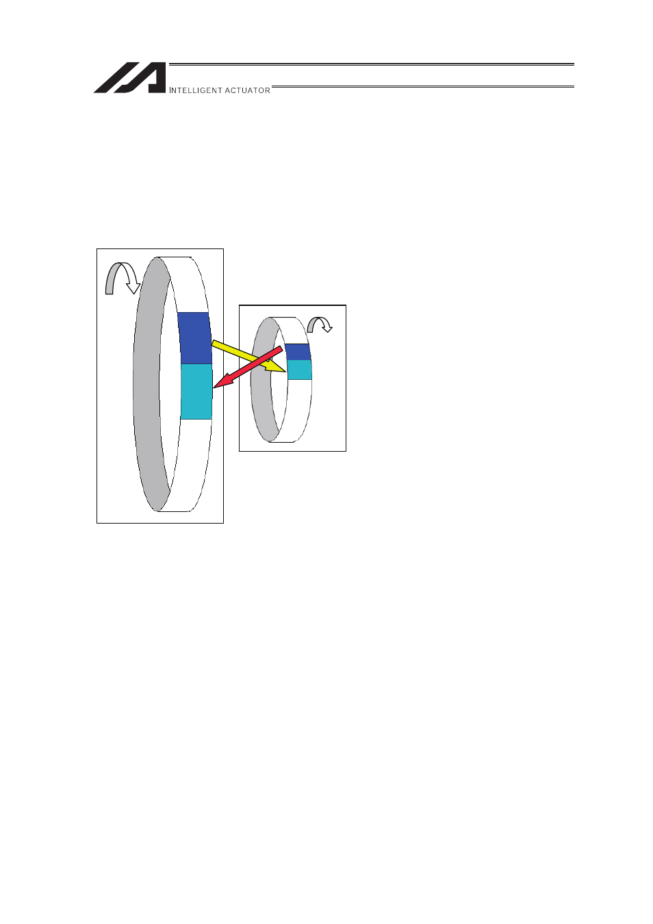
�Operation Image
Also, if one tries to read the signal that is being re-written by the other, the signal may be read wrong.
Make sure to read the signal after the rewriting is complete. (It is recommended to have more than 2
scan periods to wait.) Make sure not to have the output side to change the output until the other side
completes the reading. Also, a setting is made on the input area not to receive the signal less than a
certain time to prevent a wrong reading of noise. This duration also needs to be considered.
Note1 Because this controller performs two or more processing works including program execution and
error processing, in addition to I/0 processing, the scan time is not fixed.
7. PLC Timer Setting (Reference)
Do not have the PLC timer setting to be done with the minimum setting.
Setting to “1” for 100msec timer turns on at the timing from 0 to 100msec while 10msec timer
from 0 to 10msec for some PLC.
Therefore, the process same as when there is no timer set will be conducted and a failure may
be occurred.
Set “2” as the minimum value for the setting of 10msec timer and when setting to 100msec,
use 10msec timer and set to “10”.
PLC
(e.g. scan time is 20msec)
�
Output
Process
Input
Process
As shown in the diagram, the input and output
timings of two devices that have different scan
time do not match, when transferring a signal.
There is no guarantee that PLC would read the
signal as soon as this controller signal turns
on.
In such a case, make the setting to read the
signal after a certain time that is longer than
the longer scan time to ensure the reading
process succeeds on the PLC side. It is the
same in the case this controller side reads the
signal.
In such a case, it is recommended to ensure 2
to 4 times of the scan time for the timer setting
margin.
It is risky to have the setting below the scan
time since the timer is also processed in the
scan process.
In the diagram, PLC can only read the input
once in 20msec even though this controller
output once in 1msec.
Because PLC only conducts output process
once in 20msec, ASEP/PSEP identifies the
same output status for that entire time period.
This controller
(scan time some msec)
(Note1)