Table 518. reset strap signals (sheet 1 of 2), 518 reset strap signals – Intel CONTROLLERS 413808 User Manual
Page 780
Intel
®
413808 and 413812—Clocking and Reset
Intel
®
413808 and 413812 I/O Controllers in TPER Mode
Developer’s Manual
October 2007
780
Order Number: 317805-001US
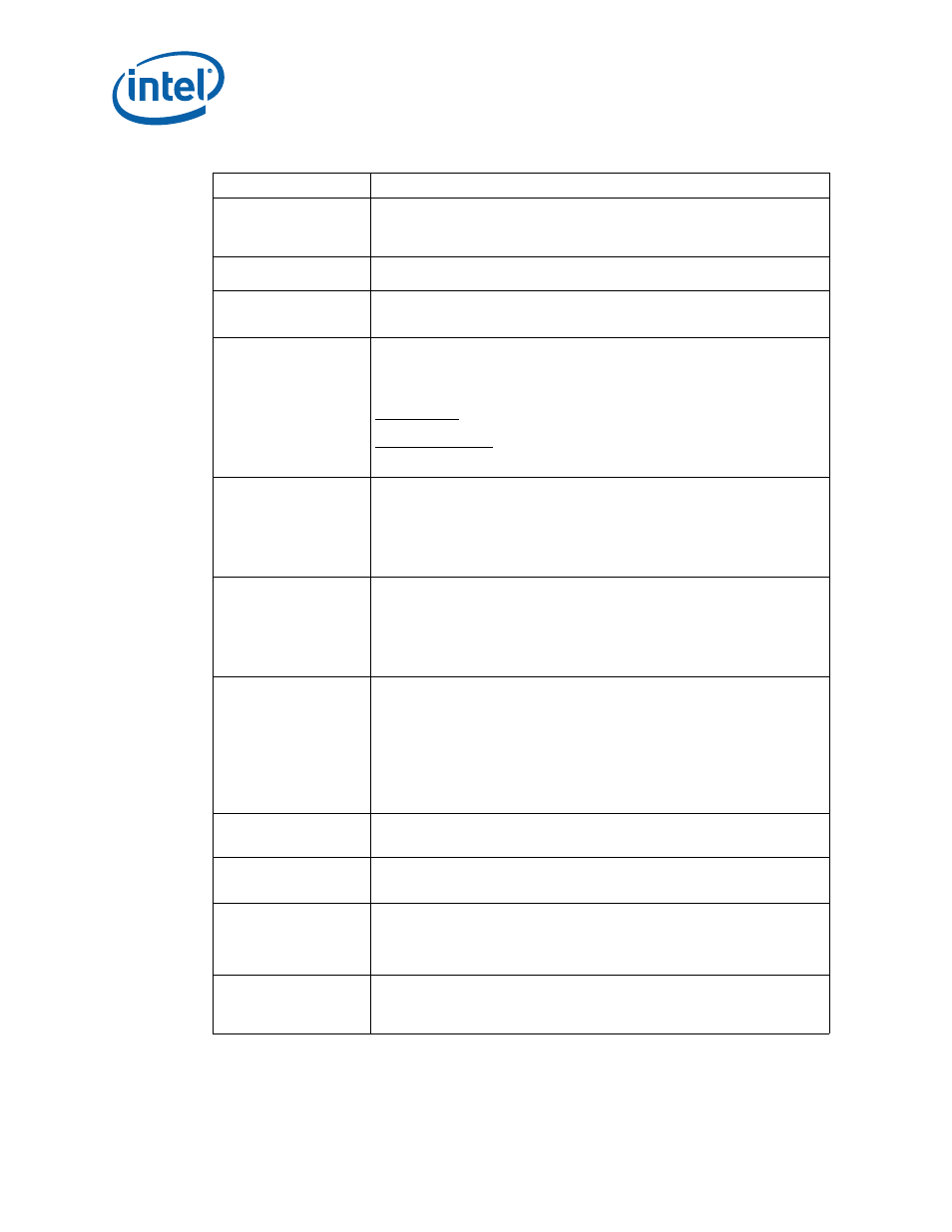
Table 518. Reset Strap Signals (Sheet 1 of 2)
Name
Description
BOOT_WIDTH_8#
PBI Boot Bus Width: I
ndicates default bus width for the PBI Memory Boot
window.
0 = 8 bits wide (Requires pull-down resistor)
1 = 16 bits wide (Default mode)
DF_SEL[2:0]
Device Function Select:
Section 17.4, “Device Function Select”
for additional details.
CONTROLLER_ONLY#
Controller only enable
0 = Controller Only. Non-TPER Mode.
1 = TPER mode.
CFG_CYCLE_EN#
Configuration Cycle Enable: Determines when the PCI interface retries
configuration cycles until the Configuration Cycle Retry bit is cleared in the ATU
(PCSR[2]).
0 = Configuration Cycles enabled (Requires pull-down resistor)
1 = Configuration Retry enabled (Default mode)
PCI-X Interface
Configuration cycles are claimed and terminated with a retry status.
PCI Express Interface
Configuration requests result in a completion TLP with Configuration Retry Status
(CRS).
HOLD_X0_IN_RST#
Core 0 Processor Reset Mode: This strap is latched at the trailing edge of reset
and reflected in Core 0 Processor Reset bit in function 0. See
“Intel XScale® Processor Reset Mechanism”
When asserted, the associated Intel XScale
®
processor is held in reset until
software clears the Core 0 Processor Reset bit.
0 = Hold in reset (Requires pull-down resistor)
1 = Don’t hold in reset (Default mode).
HOLD_X1_IN_RST#
Core 1 Processor Reset Mode: This strap is latched at the trailing edge of reset
and reflected in Core 1 Processor Reset bit in function 0. See
“Intel XScale® Processor Reset Mechanism”
When asserted, the associated Intel XScale
®
processor is held in reset until
software clears the Core 1 Processor Reset bit.
0 = Hold in reset (Requires pull-down resistor)
1 = Don’t hold in reset (Default mode).
INTERFACE_SEL_PCIX#
Selects the active interface and determines the address map for the PMMR
registers. See the MMR chapter for details.
0 = PCI-X is active
1 = PCI Express is active (default mode)
When both interfaces are active, this strap selects the ATU that is function 0 in the
internal address map
Note:
For dual interface designs, INTERFACE_SEL_PCIX# must be set
consistent with
PCIE_RC#
/
PCIX_EP#
. When operating with one
interface as an endpoint and the other interface as a root complex.
INTERFACE_SEL_PCIX# must correspond to the end point interface.
PCIE_RC#
PCI Express Root Complex: determines when the PCI Express interface operates
as an endpoint or root complex.
1 = Endpoint (Default Mode).
PCIX_EP#
PCI-X End Point: determines when the PCI-X interface operates as an endpoint or
central resource.
0 = Endpoint (Requires pull-down resistor)
PCIXM1_100#
PCI Bus Mode 1 100MHz Enable: limits the maximum PCI-X mode operating
frequency to 100MHz while in mode1. Only used when ATU is acting as the central
resource for the PCI domain.
0 = Limit maximum frequency to 100MHz.(Requires pull-down resistor)
1 = 133MHz enabled (Default mode)
PCIXM2_100#
PCI-X Mode 2 133MHz Enable: limits the maximum PCI-X mode 2 operating
frequency to 100MHz while operating in mode 2.
0 = Limit maximum Frequency to 100MHz (200MHz data.
1 = 133MHz (266MHz data) enabled (Default mode)