13 inbound atu base address register 0 - iabar0, 13inbound atu base address register 0 - iabar0, 152 inbound atu base address register 0 - iabar0 – Intel CONTROLLERS 413808 User Manual
Page 304: Intel, Bit default description
Intel
®
413808 and 413812—Address Translation Unit (PCI Express)
Intel
®
413808 and 413812 I/O Controllers in TPER Mode
Developer’s Manual
October 2007
304
Order Number: 317805-001US
3.17.13 Inbound ATU Base Address Register 0 - IABAR0
The Inbound ATU Base Address Register 0 (IABAR0) together with the Inbound ATU
Upper Base Address Register 0 (IAUBAR0) defines the block of memory addresses
where the inbound translation window 0 begins. The inbound ATU decodes and
forwards the bus request to the 4138xx internal bus with a translated address to map
into 4138xx local memory. The IABAR0 and IAUBAR0 define the base address and
describes the required memory block size; see
Section 3.17.15, “Determining Block
Sizes for Base Address Registers” on page 306
. Bits 31 through 12 of the IABAR0 is
either read/write bits or read only with a value of 0 depending on the value located
within the IALR0. This configuration allows the IABAR0 to be programmed per PCI Local
Bus Specification, Revision 2.3.
The programmed value within the base address register must comply with the PCI
programming requirements for address alignment. Refer to the PCI Local Bus
Specification, Revision 2.3 for additional information on programming base address
registers.
By default the first 8 Kbytes of memory defined by the IABAR0, IAUBAR0 and the
IALR0 is reserved for the Messaging Unit.
Warning:
When IALR0 is cleared prior to host configuration, the user should also clear the
Prefetchable Indicator and the Type Indicator. Assuming IALR0 is not cleared:
a. Since non prefetchable memory windows can never be placed above the 4 Gbyte
address boundary, when the Prefetchable Indicator is cleared prior to host
configuration, the user should also set the Type Indicator for 32 bit
addressability.
b. For compliance to the PCI-X Protocol Addendum to the PCI Local Bus
Specification, Revision 2.0, when the Prefetchable Indicator is set prior to host
configuration, the user should also set the Type Indicator for 64 bit
addressability. This is the default for IABAR0.
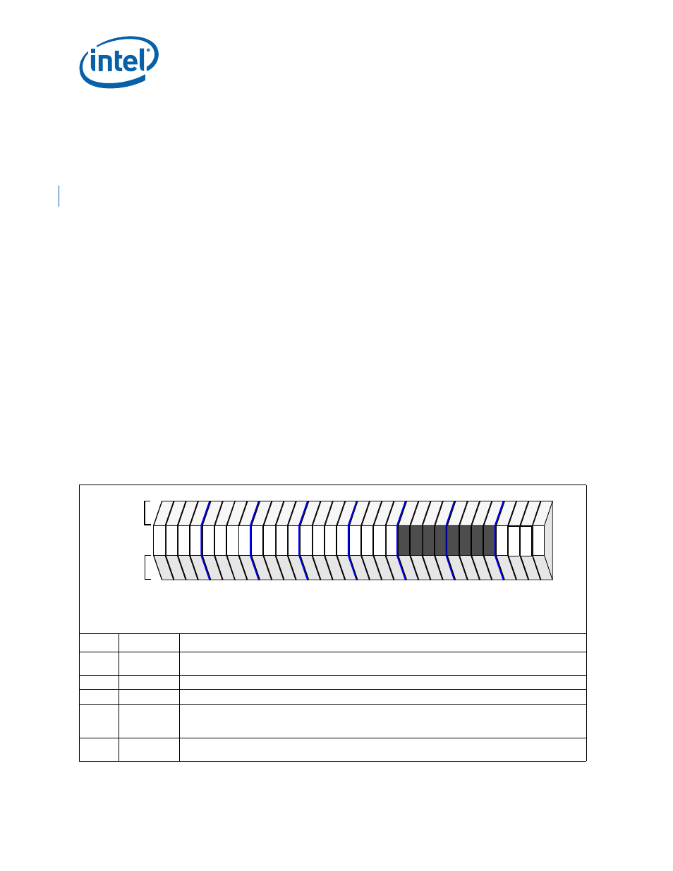
Table 152. Inbound ATU Base Address Register 0 - IABAR0
Bit
Default
Description
31:12
00000H
Translation Base Address 0 - These bits define the actual location the translation function is to respond
to when addressed from the PCI Express Link.
11:04
00H
Reserved.
03
1
2
Prefetchable Indicator - When set, defines the memory space as prefetchable.
02:01
10
2
Type Indicator - Defines the width of the addressability for this memory window:
00 - Memory Window is locatable anywhere in 32 bit address space
10 - Memory Window is locatable anywhere in 64 bit address space
00
0
2
Memory Space Indicator - This bit field describes memory or I/O space base address. The ATU does not
occupy I/O space, thus this bit must be zero.
PCI
IOP
Attributes
Attributes
28
24
20
16
12
8
4
0
31
rw
rw
rw
rw
rw
rw
rw
rw
rw
rw
rw
rw
rw
rw
rw
rw
rw
rw
rw
rw
rw
rw
rw
rw
rw
rw
rw
rw
rw
rw
rw
rw
rw
rw
rw
rw
rw
rw
rw
rw
rv
rv
rv
rv
rv
rv
rv
rv
rv
rv
rv
rv
rv
rv
rv
rv
rw
ro
rw
ro
ro
ro
ro
ro
Attribute Legend:
RV = Reserved
PR = Preserved
RS = Read/Set
RW = Read/Write
RC = Read Clear
RO = Read Only
NA = Not Accessible
Internal Bus Address Offset
+010H