42 atu interrupt status register - atuisr, 42atu interrupt status register - atuisr, 69 atu interrupt status register - atuisr – Intel CONTROLLERS 413808 User Manual
Page 181: Atu interrupt status register - atuisr” on, Processor, Address translation unit (pci-x)—intel, Bit default description, P_serr
Intel
®
413808 and 413812 I/O Controllers in TPER Mode
October 2007
Developer’s Manual
Order Number: 317805-001US
181
Address Translation Unit (PCI-X)—Intel
®
413808 and 413812
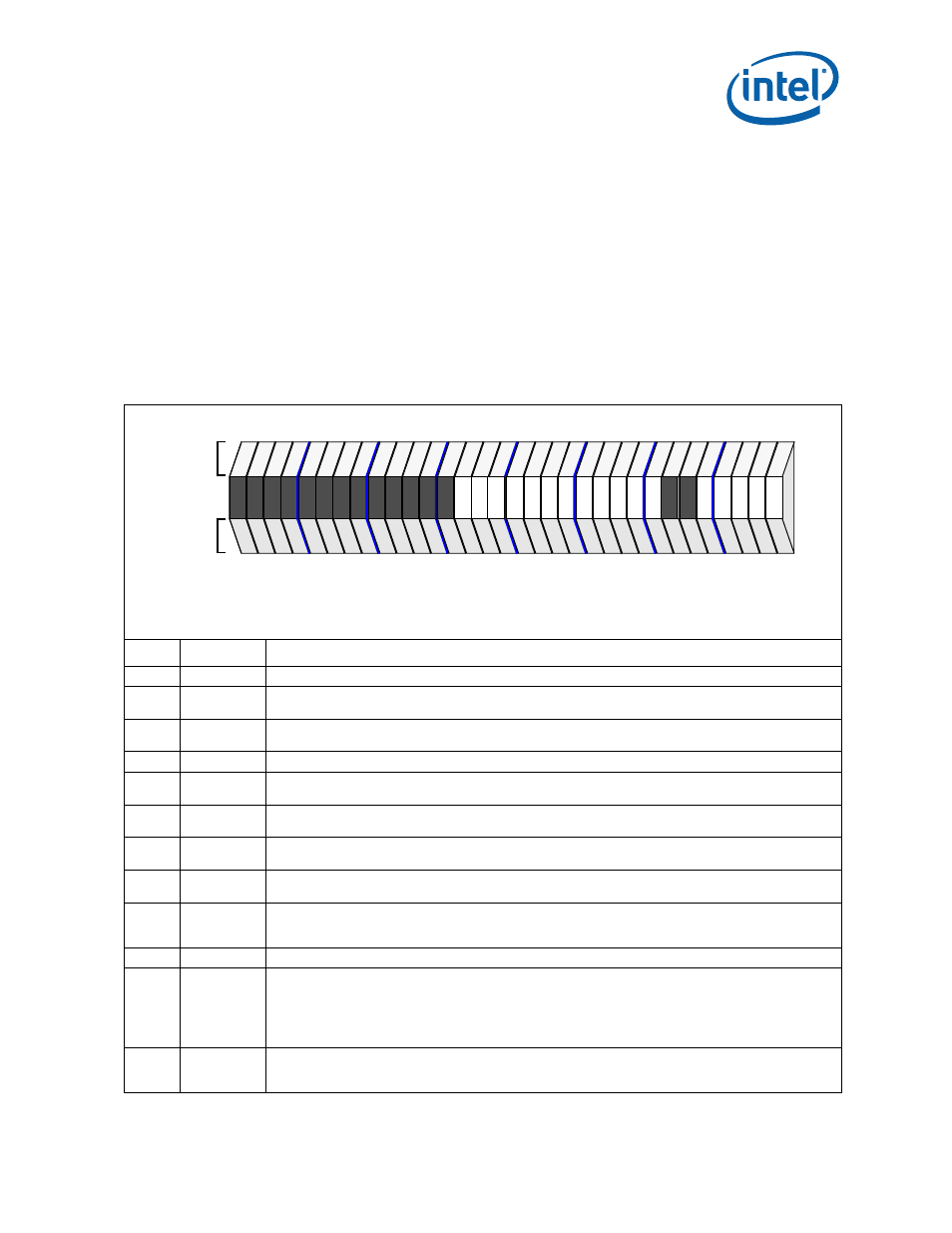
2.14.42 ATU Interrupt Status Register - ATUISR
The ATU Interrupt Status Register is used to notify the core processor of the source of
an ATU interrupt. In addition, this register is written to clear the source of the interrupt
to the interrupt unit of the 4138xx. All bits in this register are Read/Clear.
Bits 4:0 are a direct reflection of bits 14:11 and bit 8 (respectively) of the ATU Status
Register (these bits are set at the same time by hardware but need to be cleared
independently). Bit 7 is set by an error associated with the internal bus of the 4138xx.
Bit 8 is for software BIST. The conditions that result in an ATU interrupt are cleared by
writing a 1 to the appropriate bits in this register.
Note that bits 4:0, and bits 15 and 13:7 can result in an interrupt being driven to the
Intel XScale
®
processor.
Table 69. ATU Interrupt Status Register - ATUISR (Sheet 1 of 2)
Bit
Default
Description
31:19
0000H
Reserved
18
0
2
PCI Interface Error - This bit is set when any PCI interface error occurs. When set, this bit results in the
assertion of the ATU PCI Interface Error Interrupt.
17
0
2
VPD Address Register Updated - This bit is set when a PCI bus configuration write occurs to the VPDAR
register. When set, this bit results in the assertion of the ATU Config Reg Write Interrupt.
16
0
2
Internal Bus Parity Error Detected - This bit is set when an Internal Bus Parity Error is detected.
15
0
2
ATU Configuration Write - This bit is set when a PCI bus configuration write occurs to any enabled
function. When set, this bit results in the assertion of the ATU Config Reg Write Interrupt.
14
0
2
Detected Correctable Error - This bit is set in PCI-X Mode 2 only when the 4138xx detects a single bit
ECC error in any phase of a PCI transaction.
13
0
2
Initiated Split Completion Error Message - This bit is set when the device initiates a Split Completion
Message on the PCI Bus with the Split Completion Error attribute bit set.
12
0
2
Received Split Completion Error Message - This bit is set when the device receives a Split Completion
Message from the PCI Bus with the Split Completion Error attribute bit set.
11
0
2
Power State Transition - When the Power State Field of the ATU Power Management Control/Status
Register is written to transition the ATU function Power State from D0 to D3, D0 to D1, or D3 to D0 and
the ATU Power State Transition Interrupt mask bit is cleared, this bit is set.
10
0
2
P_SERR#
Asserted - set when
P_SERR#
is asserted on the PCI bus by the ATU.
09
0
2
Detected Parity Error - set when a parity error is detected on the PCI bus even when the ATUCMD
register’s Parity Error Response bit is cleared. Set under the following conditions:
• Uncorrectable Write Data Error when the ATU is a target (inbound write).
• Uncorrectable Read Data Error when the ATU is an initiator (outbound read).
• Any Uncorrectable Address or Attribute (PCI-X Only) Error on the Bus.
08
0
2
ATU BIST Interrupt - When set, the host processor has set the start BIST, ATUBISTR register bit 6, and
the ATU BIST interrupt enable (ATUCR register bit 3) is enabled. The Intel XScale
®
processor can initiate
the software BIST and store the result in ATUBISTR register bits 3:0.
PCI
IOP
Attributes
Attributes
28
24
20
16
12
8
4
0
31
rv
rv
rv
rv
rv
rv
rv
rv
rv
rv
rv
rv
rv
rv
rv
rv
rv
rv
rv
rv
rv
rv
rv
rv
rv
rv
rc
ro
rc
ro
rc
ro
rc
ro
rc
ro
rc
ro
rc
ro
rc
ro
rc
ro
rc
ro
rc
ro
rc
ro
rv
rv
rv
rv
rc
ro
rc
ro
rc
ro
rc
ro
rc
ro
Attribute Legend:
RV = Reserved
PR = Preserved
RS = Read/Set
RW = Read/Write
RC = Read Clear
RO = Read Only
NA = Not Accessible
Register Offset
+078H