8 diagnostics, Diagnostics, 9"can on board" system bus – Lenze 9400 User Manual
Page 327
Lenze · Servo-Inverter 9400 HighLine · Reference manual · DMS 10.0 EN · 11/2013 · TD05/06
327
9
"CAN on board" system bus
9.8
Diagnostics
_ _ _ _ _ _ _ _ _ _ _ _ _ _ _ _ _ _ _ _ _ _ _ _ _ _ _ _ _ _ _ _ _ _ _ _ _ _ _ _ _ _ _ _ _ _ _ _ _ _ _ _ _ _ _ _ _ _ _ _ _ _ _ _
9.8
Diagnostics
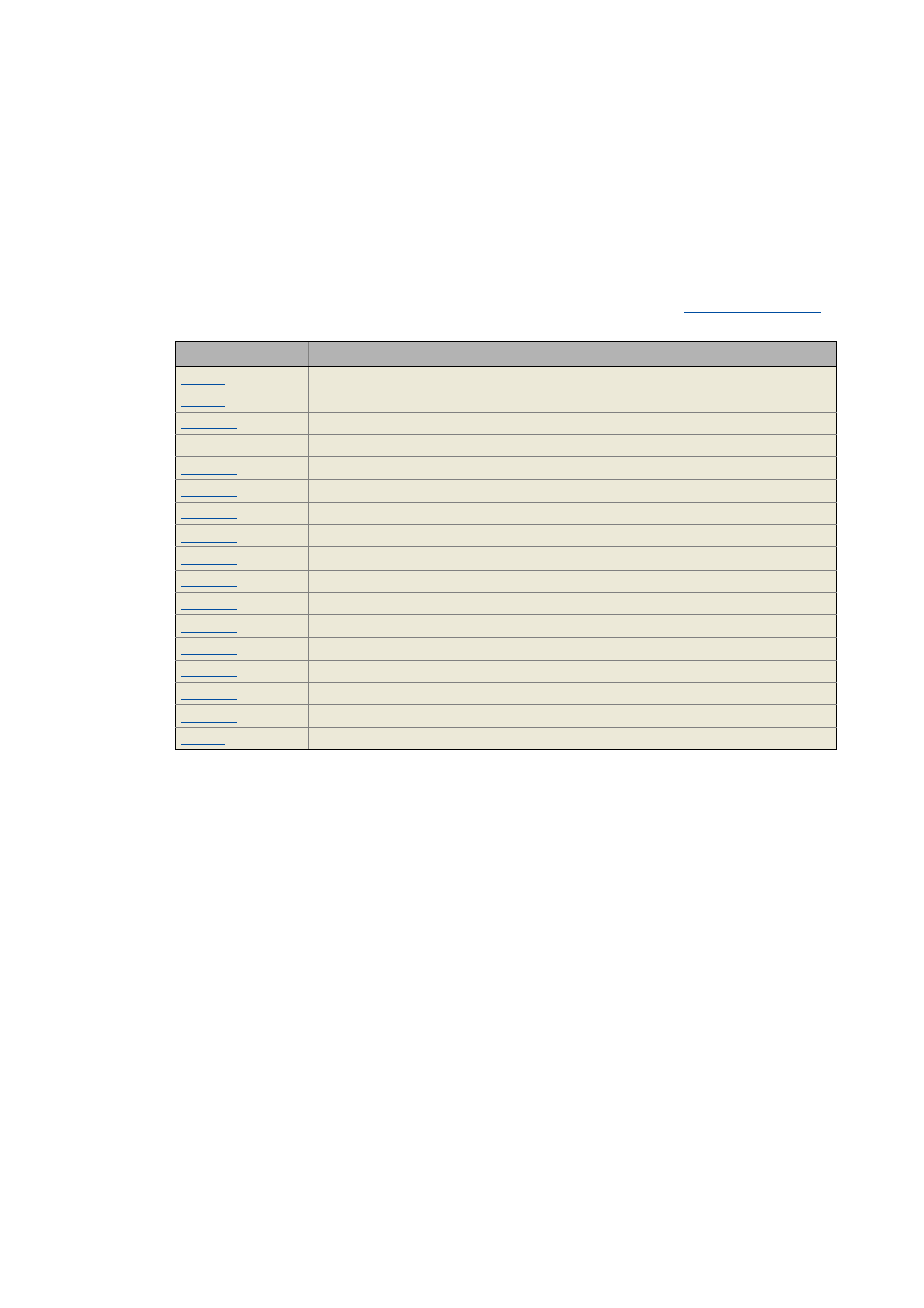
The display parameters listed in the following table serve to request current information on the
system bus for diagnostic purposes, e.g. using the keypad, via a bus system, or using »Engineer«
(when an online connection has been established to the controller).
• The »Engineer« parameter list and the keypad contain these parameters in the category
CAN CAN management.
• A detailed description of these parameters can be found in the chapter "
Parameter
Display
CAN error
CAN status
CAN stuffing bit error counter
CAN format error counter
CAN acknow. error counter
CAN bit 1 error counter
CAN bit 0 error counter
CAN CRC error counter
CAN Tx telegram counter
CAN Rx telegram counter
CAN bus load: Current node load in Tx direction
CAN bus load: Current node load in Rx direction
CAN bus load: Current node load of faulty telegrams
CAN bus load: Node peak load in Tx direction
CAN bus load: Node peak load in Rx direction
CAN bus load: Node peak load of faulty telegrams
CAN error register (DS301V402)