6 "state bus" monitoring function, State bus" monitoring function, State bus" monitoring function ( 283) – Lenze 9400 User Manual
Page 283: 8i/o terminals
Lenze · Servo-Inverter 9400 HighLine · Reference manual · DMS 10.0 EN · 11/2013 · TD05/06
283
8
I/O terminals
8.6
"State bus" monitoring function
_ _ _ _ _ _ _ _ _ _ _ _ _ _ _ _ _ _ _ _ _ _ _ _ _ _ _ _ _ _ _ _ _ _ _ _ _ _ _ _ _ _ _ _ _ _ _ _ _ _ _ _ _ _ _ _ _ _ _ _ _ _ _ _
8.6
"State bus" monitoring function
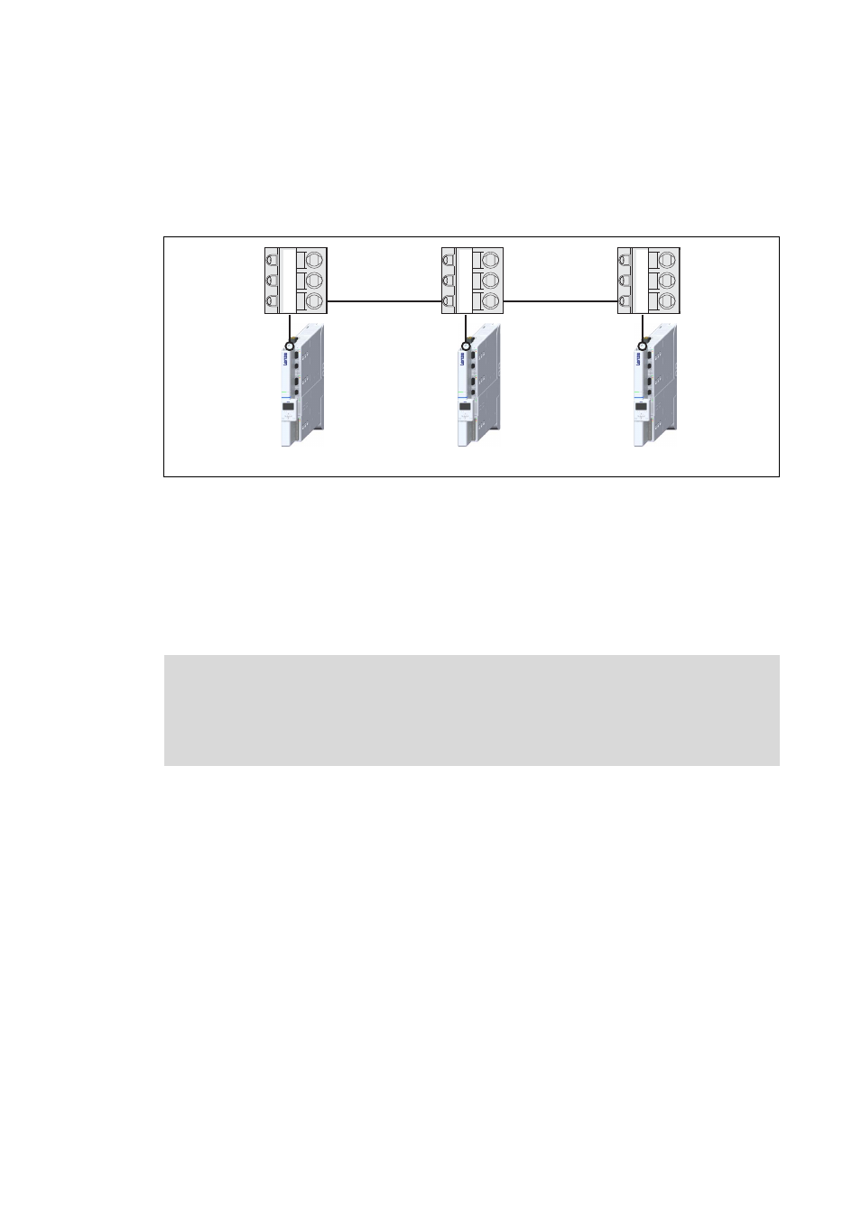
The state bus is a bus system that is solely designed for Lenze controllers, via which up to 20
controllers can be connected to each other, and by means of which the function of a "release cord"
can be simulated:
[8-1]
Schematic diagram: Networking via state bus
• The state bus only knows the states "OK" and "Error".
• The state bus is a bus with multi-master capability, i.e. each node connected to the state bus can
set the state bus to the "Error" state by setting it to LOW level.
• In the "Error" status, all nodes start their adjustable response, e.g. synchronised braking of the
drive system.
• The "Error" state is also set if a node connected to the state bus is not supplied with voltage.
X2/SB = State bus In/Out (reference potential GE)
X2
X2
X2
GE
24E
SB
GE
24E
SB
GE
24E
SB
Note!
Exception handling:
• In the case of a critical exception within the application (e. g. reset), the "release cord"
is not triggered, the state bus remains in the "OK" status.